How to determine the inductance of a coil ?

Art Vandelay

Joined Nov 1, 2024
140
wait, are you sure? The original formula was L = 1 / ((2π * fv)^2 * C)
now you show me that L = 1 / (2π^2 * fv^2 * C) which is different:
L = 1 / (2π^2 * fv^2 * C)
L = 1 / (9.8690 * 238090^2 * 0.0000001)
L = 1 / (9.8690 * 56686848100 * 0.0000001)
L = 1 / 55944.25038989
L = 1.78749e-5
L = 0.0000178749
L = 17.8uH (gaaaaaaah - still wrong!) - it should be 2.5mH

wait -100R but where?
L = 100 / (2π^2 * fv^2 * C) -I'll put it here
L = 100 / 55944.250
L = 0.00178
L = 1.78mH -yah, very close to the truth ! (should be 2.5mH)
Where did you get 100 from? If you changed the resistor from 10 to 100 (to reduce the current), the expression remains unchanged.

Using a 100nF capacitor and 2.5mH inductor you should get:

L = 1 / ((2π * f)^2 * C)
L = 1 / ((2π * 238090)^2 * (100 x 10^-9))
L = 4.46846080873 x 10^-6 = 5uH (rounded to the correct number of significant figures)

It's best to compute the entire expression at once to reduce rounding error propagation. Find a calculator that allows you to enter everything at once then round at the end.

Note that larger value capacitors will result in bigger errors in the formula. A typical cap has an error of +- 20%. So, for a 100nF cap, the error will be +-20nF. That will throw off the result quite a bit. Similarly, any error in measuring the resonant frequency will have an effect.

Assuming you really are using a 100nF capacitor and 2.5mH inductor, the resonant frequency is 10.0658kHz. Try starting over because the difference between the calculated frequency is an order of magnitude lower than what you measured. This suggests the inductor is mislabeled or your scope is faulty or improperly configured.

https://www.omnicalculator.com/physics/resonant-frequency-lc
 

MrAl

Joined Jun 17, 2014
13,859
i measured it before installing, and is 101nF, to be very precise.
---
I used your measurement from before of the 225kHz !
L = 100 / (2π^2 * fv^2 * C)
L = 100 / (9.8690 * 225000^2 * 0.0000001) with 225kHz
L = 100 / (9.8690 * 50625000000 * 0.0000001)
L = 100 / 49961.8125
L = 0.002001
L = 2.001mH <<< NOICE !!! Very-very close.
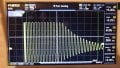
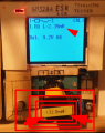
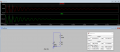
My tester was: View attachment 335269
Now, that we find the formula and the way to measure it, -How to increase the reading resolution on it?
My osc is not letting me read too deep/zoomed in because is showing a blank if its too zoomed in.
I have to keep a certain distance (from the H knob) to actually display anything.
Are you still using the following values:
R=10 Ohms
C=0.1uf
L=presumed to be around 2.5mH

?

The resonant frequency formula is void of any current or voltage measurements. However, in order to measure this frequency properly you often need a frequency generator with a low impedance output. That's so that they amplitude of the generator does not change as the circuit loads it with different frequencies.
Because you have a series resistance of 10 Ohms, your generator would have to have an output impedance less than 1 Ohm, and with that scope that's not going to be the case. It may be as high as 600 Ohms. You'll have to check this and possibly use a buffer amplifier.

You may not be able to rely on the transient analysis ring frequency either. That's often close to the resonant frequency, but not always. The more usual test is to change the frequency little by little until you see either peak in output voltage or a dip (valley) in the output voltage, and then that's the physical resonant frequency.
If R is of a low enough value, the transient method (square wave, pulse, etc.) can show a ring frequency very close to the actual resonant frequency for which that formula applies. To know for sure you have to do a little calculation.
For your L and C values, we have the following little table:
fr=[5032.921210448703, 5031.662822827972, 5027.885770258039]
and these are the resonate frequencies for values of R=0, R=10, and R=20 respectively:
R=[0, 10, 20]

so we can see that the frequency is close with a value of R=10, but that's a low value for a regular frequency generator to be able to handle.
 

Thread Starter

q12x

Joined Sep 25, 2015
2,245
if you choose your points wider (several periods) you can divide by "several" to get better accuracy.
I did another test and I did what you just said here - I widen the time period.
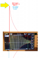
This is another reading. Notice the green vertical markers, and the top left corner data from them.
20241107_073038.jpg
I also numbered the squares and I have 10.4 from marker to marker, which means 104us exactly like that top-left panel is showing.
So, the new data into the formula:
with 104us/24pulses=4.333us=230.786kHz
L = 100 / (2π^2 * fv^2 * C)
L = 100 / (9.8690 * 230786^2 * 0.0000001) with 230kHz
L = 100 / (9.8690 * 53262177796 * 0.0000001)
L = 100 / 52564.4432668724
L = 0.0019024
L = 1.9mH
 
Last edited:

MrAl

Joined Jun 17, 2014
13,859
Where did you get 100 from? If you changed the resistor from 10 to 100 (to reduce the current), the expression remains unchanged.

Using a 100nF capacitor and 2.5mH inductor you should get:

L = 1 / ((2π * f)^2 * C)
L = 1 / ((2π * 238090)^2 * (100 x 10^-9))
L = 4.46846080873 x 10^-6 = 5uH (rounded to the correct number of significant figures)

It's best to compute the entire expression at once to reduce rounding error propagation. Find a calculator that allows you to enter everything at once then round at the end.

Note that larger value capacitors will result in bigger errors in the formula. A typical cap has an error of +- 20%. So, for a 100nF cap, the error will be +-20nF. That will throw off the result quite a bit. Similarly, any error in measuring the resonant frequency will have an effect.

Assuming you really are using a 100nF capacitor and 2.5mH inductor, the resonant frequency is 10.0658kHz. Try starting over because the difference between the calculated frequency is an order of magnitude lower than what you measured. This suggests the inductor is mislabeled or your scope is faulty or improperly configured.

https://www.omnicalculator.com/physics/resonant-frequency-lc
It's close, but not exact. The frequency will come down by about 120Hz with R=100 rather than R=10.
 

Thread Starter

q12x

Joined Sep 25, 2015
2,245
L=presumed to be around 2.5mH
presuming nothing - here is the proof:
1730959905191.png
Assuming you really are using a 100nF capacitor
presuming nothing - it is a 101nF cap, I measure it before installing it in the circuit. Because I measured other 104(100nF) before it and I got 83nF so I had to measure a couple until I find this one that I use. Im not playing Tzurka here. So when Im saying Im using something, I am.
 

MrAl

Joined Jun 17, 2014
13,859
presuming nothing - here is the proof:
View attachment 335273

presuming nothing - it is a 101nF cap, I measure it before installing it in the circuit. Because I measured other 104(100nF) before it and I got 83nF so I had to measure a couple until I find this one that I use. Im not playing Tzurka here. So when Im saying Im using something, I am.
Hi,

Well with inductance, it's always going to be a bit of a presumption because of the difficulty in specifying inductors especially with magnetic cores. I will use that 2.5mH as a target value anyway though at least for now.

BTW there is another test you can do where you measure the voltage across the cap. You can then approximate the inductor value that way also. You can then compare measurements.
 

Thread Starter

q12x

Joined Sep 25, 2015
2,245
BTW there is another test you can do where you measure the voltage across the cap. You can then approximate the inductor value that way also. You can then compare measurements.
ok, explain in detail what I should do.
 

Art Vandelay

Joined Nov 1, 2024
140
I did another test and I did what you just said here - I widen the time period.
This is another reading. Notice the green vertical markers, and the top left corner data from them.
View attachment 335272
I also numbered the squares and I have 10.4 from marker to marker, which means 104us exactly like that top-left panel is showing.
So, the new data into the formula:
with 104us/24pulses=4.333us=230.786kHz
L = 100 / (2π^2 * fv^2 * C)
L = 100 / (9.8690 * 230786^2 * 0.0000001) with 230kHz
L = 100 / (9.8690 * 53262177796 * 0.0000001)
L = 100 / 52564.4432668724
L = 0.0019024
L = 1.9mH
100 still doesn't belong in the expression.

One possibility for the error is you have a large amount of capacitance in series with the 100nF cap. If the additional capacitance is very small, it will dominate the 100nF cap you have installed. Series capacitors behave like parallel resistors so the lowest value dominates.

Provided the resonant frequency is truly 238kHz and the inductor is 2.5mH, the capacitance needed to resonate at this frequency is 0.17nF. This suggests you have around 0.17nF of capacitance in series with the actual 100nF capacitor. 170pF is a lot of capacitance but this could account for the resonant frequency you are seeing. Is it possible your breadboard and / or wires are adding this much capacitance? Other than that, I'm not sure what's going on.
 

Thread Starter

q12x

Joined Sep 25, 2015
2,245
Hahaha- Huston, it appears I made a mistake. The capacitor was on the table.
I was getting these results from the last circuit from @panic mode in #30. But I put 100R in series because I was getting too much heat on the coil. Thats it, no capacitor.
So my mistake was that I jumped into the formula and somehow it remained in my memory that I used that 100nF, but nothing was in the circuit. I was paying my full attention to the osciloscope screen and to its knobs to catch something. Thats why this error occurred.
So... Can't we use the function, without the capacitor in it? replacing it with a 1 or something? or with that 170pF that you mentioned earlier?
The problem now, after inserting the Cap, it is not working from the button press, like it was before, without the cap. Thats why Im saying if its not possible to take the cap out of the equation or replace its value with something else.
 
Last edited:

Thread Starter

q12x

Joined Sep 25, 2015
2,245
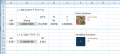
I finally made a small Excel calculator for both these 2 functions which none are good so far. But we are getting there.
1730973281945.png
Only that in Panic function the Cap is not existent and thats why I made the mistake. Ha. - But the circuit worked !
And on Vandelay the circuit doesnt work, at least with the button and the cap.
Im mute at this point !
 
Last edited:

Art Vandelay

Joined Nov 1, 2024
140
I finally made a small Excel calculator for both these 2 functions which none are good so far. But we are getting there.
View attachment 335301
Only that in Panic function the Cap is not existent and thats why I made the mistake. Ha. - But the circuit worked !
And on Vandelay the circuit doesnt work, at least with the button and the cap.
Im mute at this point !
If you look closely at Panic Mode's formula from post #38 and EricGibbs from post #52, you'll find they are equal to mine. The difference is how we manipulated the algebra. They are all derived from f = 1 / (2π √ (L * C)) which is the resonant formula. You changed the 1 to 100 in Panic's formula for some reason but that's not right!

1 / ((2π * f)^2 * C) = 1 / ((2π)^2 * f^2 * C)) = 1 / (4π^2 * f^2 * C)

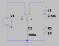
Try building Dankos circuit in post #53 with a SPDT switch. The cap will be charged to 5 volts when the switch is in the left position.

When it's switched to the right position, the cap will discharge through the inductor towards ground and the energy will be reflected back and forth between the cap and inductor with a resonant frequency determined by the cap and inductor values.

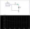
Plug in the frequency and capacitance into any of three formulas above and you'll get the unknown inductance. Using the values seen below, you should see a resonant frequency close to 10.0658kHz on the scope. MrAi made some good points regarding scopes but I don't have the expertise to comment on the details.

1.png

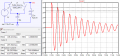
Here is what you should see when the cap discharges from 5V:

2.png
 

MrAl

Joined Jun 17, 2014
13,859
ok, explain in detail what I should do.
Hi,

You can use this formula:
Ampl=Eac/sqrt(w^2*C^2*R^2+(1-w^2*C*L)^2)
where
Ampl is the amplitude of the voltage across C the cap,
Eac is the amplitude of the input AC voltage,
C is capacitance,
L is inductance,
w =2*pi*f with f the frequency in Hertz,
R is the series resistance you are using (10 Ohms although you could change that).
With this though you have to stay away from the resonate frequency, and really it works better with just a resistor and inductor and no cap. Then the voltage across the resistor is:
Ampl=Eac*R/sqrt(R^2+w^2*L^2)

A usual test frequency is 1kHz but you can go up higher and check at several different frequencies.
You should try this and compare, and check the results at least at three different frequencies, maybe 1kHz, 2kHz, and 4kHz for example.

I'd like to see the results of this test too.
You should use the scope not a meter. You should also look at the input voltage from the generator so you can make sure you have the right result if the output of the generator changes with frequency. The formula still applies, but you have to then change Eac.

Just in case you want to look at the voltage across the inductor with the non-cap version, the formula is:
Ampl=(w*L)/sqrt(R^2+w^2*L^2)

I hope you can do this and post the results it will be interesting.
 

panic mode

Joined Oct 10, 2011
5,420
I put 100R in series because I was getting too much heat on the coil.
you must have wired it wrong... there is not supposed any noticeable heat.
energy that can be stored in capacitor is limited by voltage to which it is charged. and this is proportional to square of voltage. so 1/3 of the voltage means 1/9 of the energy and heat... and that reduction is an order of magnitude....

Ec=C*V^2/2
C=100nF
V=5V
Ec= 12.5uJ (that is micro Joule).
suppose this decays on 30 cycles 10us long, that is 300us
so power is dE/dt=12.5uJ/300us=0.041W

this is way too small to feel as heat.... definitely not enough to be considered "too much heat on the coil"
 

panic mode

Joined Oct 10, 2011
5,420
Only that in Panic function the Cap is not existent and that's why I made the mistake. Ha. - But the circuit worked !
not sure what you mean, the cap is part of the circuit and equation. and your equation is using factor 100 for some reason. as Art already mentioned, this is not correct.
 

MrChips

Joined Oct 2, 2009
35,276
Use an NE555 timer circuit to generate a square wave.
Measure the L/R time constant (the time it takes the signal to fall to 37%) on the oscilloscope.

L = R x time constant

RL time constant.jpg
 

panic mode

Joined Oct 10, 2011
5,420
i think i see the problem... using higher voltage produces involved higher energy.

100V is 20x higher than 5V. and since square is involved, power is 400x higher. so you are encountering some 15+ Watts of heat.
1730986682698.png


you are only supposed to MEASURE inductance, not build replicas of ACME products
 
Last edited:
Top