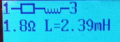
hi q,You might be on something, suggesting a higher voltage actually. My FNIRSI sig gen is a couple of 10's to 100's mV in amplitude.
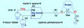
you are speaking about its output, I am speaking about its inputs.That freq module outputs only a sweeping frequency
What function generator do you use?
and how do I use it? provide some steps what to do, what to read, what to expect.one an go real basic, without function generator
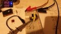
View attachment 335222


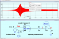
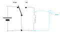
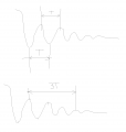
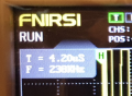
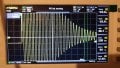
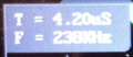
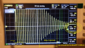
Alright ! I think I got it. But it was the 20-est time !!!! this waveform to --finally-- catch it. It was very obscured or hidden in the settings of the oscilloscope, I had to do A LOT of knobs tweaking until I got it like that. Also the waveform doesn't appear just like that, it is randomly appearing, so only sometimes, not at every button press. So that was also a disadvantage I didn't know I had it. I got lucky to catch it, while I was doing something else, playing with the knobs. And then I bring it big into focus like is here in the picture. WOW. This is the first time in my LIFE!!! when Im catching such nice waveform. Again, guided only by pure luck. Wow. I cant believe my eyes I got such glorious waveform there. But everyone here helped me formulate what to expect and when I seen a glimpse of it, I jump on it like a tiger on fire. So your participation, helped, everyone so far.put switch in charge position (choose suitable voltage such as 5VDC or whatever). connect unknown coil, connect scope, flip switch to test position. read the frequency or if you like use cursors and place them on peaks. and measure time between them. that is period T.
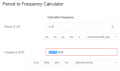
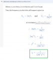
frequency is f= 1/T

V=


i measured it before installing, and is 101nF, to be very precise.are you sure that capacitor value is really 100nF and not 220nF for example?

| Thread starter | Similar threads | Forum | Replies | Date |
|---|---|---|---|---|
| Y | exctracting loop inductance from S-parameters | PCB Layout , EDA & Simulations | 0 | |
| M | Inductance values versus voltage? | Analog & Mixed-Signal Design | 3 |