Facebook
 Google
 GitHub
 Linkedin
Hello,
This is my first post ever on this forum") During the lockdown, I decided to relaunch one of my very old project: building a modular synthesizer. Not by copying without knowing what I'm doing but by trying to design by myself (not starting from scratch though). I read a lot of books including make synthesizers of the art of electronics focusing on the basics and oscillators.
During the lockdown, I decided to relaunch one of my very old project: building a modular synthesizer. Not by copying without knowing what I'm doing but by trying to design by myself (not starting from scratch though). I read a lot of books including make synthesizers of the art of electronics focusing on the basics and oscillators.
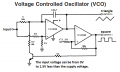
In my learning quest, I found this nice oscillator design that seems good for the first module of my synth: the VCO. (so yes, it's a copy, but it's for learning purposes )
Yet, probably there's something I don't understand yet : how can I transform this oscillator to a VCO ?
I mean: modifying R5/C1 permit to change the frequency. But how can I change it by increment of volts through a control voltage (all I want for now is a linear control voltage in the audio range)?
I think to FET as a resistor (not linear) and I tried to put a current source at various point without much success... (I'm ready to be ashamed) )
Thank you for your help !

This is my first post ever on this forum
During the lockdown, I decided to relaunch one of my very old project: building a modular synthesizer. Not by copying without knowing what I'm doing but by trying to design by myself (not starting from scratch though). I read a lot of books including make synthesizers of the art of electronics focusing on the basics and oscillators.In my learning quest, I found this nice oscillator design that seems good for the first module of my synth: the VCO. (so yes, it's a copy, but it's for learning purposes
) Yet, probably there's something I don't understand yet : how can I transform this oscillator to a VCO ?
I mean: modifying R5/C1 permit to change the frequency. But how can I change it by increment of volts through a control voltage (all I want for now is a linear control voltage in the audio range)?
I think to FET as a resistor (not linear) and I tried to put a current source at various point without much success... (I'm ready to be ashamed
) )Thank you for your help !