Is't possible to get central tap from ordinary transformer without rewinding?
I have a 15 v 2amp ordinary transformer which I want to know how to get the central tap without rewinding
It's not about rewinding it's about a transformer with a 15 volt 2 amp secondary and if it had a center tap you would have two 7.5 volt outputs at 1 amp. No there is no way to change what you have. If you want a 15 volt CT transformer you buy one. That is about as good as it gets.
If you have a transformer with two secondaries, then you have some configuration possibilities. With one primary and one seconadary, @Reloadron has given you the scoop.
I was giving an inverter project to work out and the project has central tap transformer on it, but the transformer I have with me is non central tap. I want to know how to work it out.
Is't possible to get central tap from ordinary transformer without rewinding?
I have a 15 v 2amp ordinary transformer which I want to know how to get the central tap without rewinding
It is unfortunate but commercially available transformers are very hard to modify in such a way. The windings are usually vacuum varnished which means the only practical way to get the windings off is to cut them off with a hacksaw. You can then rewind the transformer with any turns or center tap, but then it may make more noise too because it will not have been varnished.
Winding is not easy anyway unless you can get the core apart, which in many cases is also not easy to do because when the transformer is varnished the core laminations also get stuck together so very hard if not impossible to get apart.
So in short, it's really not practical.
If you can get a second transformer of the same kind you can parallel the primaries and place the secondaries in series, and if that gives you the right voltage then you can get away with that. Probably best to buy a new transformer or use a different approach to your circuit such as an H bridge as someone suggested.
You might also think about this. If you did manage to get the windings off an place new windings on, you may have to use a thinner gauge wire so that you can get two secondaries with the same number of turns. That would reduce the current rating so that may not work. You could only get the same current rating if you could put up with 1/2 the voltage from end to center tap.
What is the Voltage Rating of your Transformer Primary, and Secondary Windings ?
Are You using the Transformer "backwards" to create a much higher AC Voltage ?
.
.
.
Transformer may be built in the manner that core is Eplatelets in combination with I platelets. Then there is one single central bobbin and any mod is solely via re-winding. But transformer may alo be made in the manner when the core is two halves of C cores. Then typically it uses two bobbins and EACH (!) winding consists on two halves, left side half and right side half. Their inter-connections are frequently made masked as some kind of the bus between both bobbins. Let find the right wire with a tester and voila, You have the middle point at the hands.
But, for such joke You have to py much - with hlving the voltage.... However that loss You can regain by Greinacher circuit or Villard circuit.
I guess it wasn't obvious...
I forgot to say that the primary of the additional transformer must be wired in series with the existing transformer's primary.
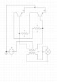
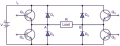
Using two identical step down transformers it would look like this.
Keep in mind when making inverters like this your output waveform is not a nice clean sine wave. You will get a square wave shape or MSW (Modified Sine Wave). The signal driving the transformer will also be a square wave which your transformer needs to work with much as your load needs to work with. The driver circuit determines the frequency. You mention a 9 volt battery. Depending on load a 9 volt PP3 type alkaline battery will be very short lived. You make no mention of anticipated load current? All of this would go much better with everything well defined.
I was giving an inverter project to work out and the project has central tap transformer on it, but the transformer I have with me is non central tap. I want to know how to work it out.
I thought the reason you used a center tap was to reverse the direction of the field in the core to prevent it saturating. I don’t see how using two transformers this way does that. Wouldn’t both transformers see a field in only one direction?
Edit to add: A bridged circuit would reverse the field.
 Facebook
 Google
 GitHub
 Linkedin