Facebook
 Google
 GitHub
 Linkedin
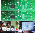
Hello, I have a small 24v DC timer module that has a momentary switch. I need the device to be powered on when powered up. So its just on when powered instead of having to push a button to start the timer cycles.
If there was a simple compact way of bypassing the momentary switching I would greatly appreciate any info how to do that. Thanks!
Ill try to link/attach a picture of the module

Mods Note:
You used the wrong file type, the png is using for simple and similar as vertical and horizontal line, the file already converted to jpg and the file size from about 700Kb to 130Kb.
If there was a simple compact way of bypassing the momentary switching I would greatly appreciate any info how to do that. Thanks!
Ill try to link/attach a picture of the module
Mods Note:
You used the wrong file type, the png is using for simple and similar as vertical and horizontal line, the file already converted to jpg and the file size from about 700Kb to 130Kb.