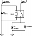
With or without the intervening relay, the solenoid is being switched by relay contacts. I don't see this as a problem for solenoid reliability. If the solenoid current is close to or greater than the 12 V relay contact rating, then adding a relay as a power amplifier makes sense. But as above, another option is a power transistor or power MOSFET.
I haven't gone back through the whole thread. Do you know the solenoid current at 24 V, or its coil resistance, or its rated coil wattage?
ak
And - welcome to AAC. This is a much friendlier forum site, and is better suited to this kind of back and forth than Stackex.
Thanks to everyone for your help! The attached document provides a basic outline of the system I'm building. Since this (fortunately!) is not an "organ builders" forum, I hope this helps electrical-computer engineering folks see how such a system works, as well as the modification I want to make, i.e. to control the solenoids with separate 24V power.
Thanks to everyone for your help! The attached document provides a basic outline of the system I'm building. Since this (fortunately!) is not an "organ builders" forum, I hope this helps electrical-computer engineering folks see how such a system works, as well as the modification I want to make, i.e. to control the solenoids with separate 24V power.
Looking at that document is appears you really just need one relay with a 12V coil matching the original valve‘s coil and contacts rated to handle the new, 24V coil. You must make sure the rating of the contacts has plenty of headroom and should use a flyback diode on the 24V solenoid if there isn’t one in place (it would be a diode across the coil’s terminals). This prevents the high voltage that is produced by back EMF when a coil is de-energized and its magnetic field collapses. The arcing will eventually destroy the relay contacts.
Basically, you will simply take the wires now on the 12V solenoid and move them to the new, 12V relay. Then you will wire the new 24V solenoid’s power through the NO contact on the new 12V relay. Nothing else is needed. Just be sure the 12V relay coil is similar to the old solenoid coil and everything will be fine.
"Y" has related what I missed stating.
and CONSIDER THAT TRANSISTORS, both bipolar and mosfet, ARE THREE TERMINAL DEVICES!!! That means that the control signal is tied to the power circuit!!
So a transistor has no place in this discussion.
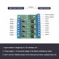
The attached image shows a MOS FET board which I think will work. Four different 12VDC relays from organ "chamber driver" wired into left terminals, control 4 different 24VDC solenoids wired into right terminals. The 24VDC power supply exclusively for solenoids is wired into topmost terminals on right, as indicated.
The attached image shows a MOS FET board which I think will work. Four different 12VDC relays from organ "chamber driver" wired into left terminals, control 4 different 24VDC solenoids wired into right terminals. The 24VDC power supply exclusively for solenoids is wired into topmost terminals on right, as indicated.
It appears that would work for your application. The reason I mentioned a relay was for the one-to-one swap with the valve which would avoid any complication arising from unknown requirements of the organ’s interface board.
I don’t expect there to be a problem, and if there is it can almost certainly be worked around, but it’s not always the case a person wants to dig around to solve such problems.

 Facebook
 Google
 GitHub
 Linkedin