How to check if an RC surge supressor is still working or not?

Thread Starter

Jalalah

Joined Jun 17, 2019
3
Hi everyone,

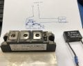
I was wondering how I can test an RC surge suppressor to see if it is still working properly? It is 0.33uF+20Ω/2W 1000V.AC, MTI-MCR-P as shown in the image below which is connected into the thyristor module/ silicon controlled rectifier (MTC-110-16) inside a furnace.


Thanks,

Jalalah
 
It's not really a surge suppressor. It's a snubber. it's purpose is to limit dv/dt, so that the triac does't turn on unexpectingly. Usually they will be found across a triac or switch.

An LCR meter should work. if the capacitor is shorted, then an ohmmeter. It's unlikely that the cap is shorted though, because it's likely and x or Y series capacitor which are specifically designed for line operation.

You can sometimes see blips when you reverse your ohmmeter leads, but the cap may not be large enough to show one.
 

Thread Starter

Jalalah

Joined Jun 17, 2019
3


Thank you for your reply. Actually, this RC snubber is not connected across the two lines of 220V AC but connected on one line (L1) as shown in the attached image. Is it possible to test it by AVOmeter? or only by LCR meter?
 

Attachments

It's nothing more than a capacitor in series with a resistor, but it's not likely to short. What do you get when you measure the resistance? I would expect a high resistance when it settles.

Then pick a low fixed scale like 1K full scale. measure and reverse the leads. Hopefully, it will blip.
 

Zoe123

Joined May 20, 2019
5
The mcr-p is tested as a RC absorber, which is used to eliminate sparks and arcs. The specific test method can test the capacitance and resistance parameters using the LCR bridge according to the parameters of the surface of the product.
 

Kjeldgaard

Joined Apr 7, 2016
476
I would say that two measurements with a multimeter can tell a lot about the state of a R/C circuit.

First a little about what usually happens with resistors and capacitors:
Resistors interrupt, more or less,
Capacitors can disconnect, leak or short-circuit.

Measure the resistance: It must be very high, some MΩ or an overflow. A low resistance means leak in the capacitor, but not enough to burn the resistor.

Measure the capacitance: It should be close to 330 nF (+/- 20% presumably). A very low value would mean a break in the resistor or capacitor and too high a capacity should not occur.
 
Do you happen to have a function generator (oscillator)? You should be able to use the magic equation of fc=1/(2*PI*R*C) and some resistors. This is the corner frequency where the output is down 0.707. Not exactly sure what the test circuit might look like. Probably a series resistor and the snubber to ground and a voltmeter out. I'd try it with two separate components first.

e.g. 400. Initially it should pass the full amplitude and then slowly start to look like a voltage divider of 400 and 20 ohms to ground.

You might be able to scope the output in your OEM circuit.

The failure mode will likely be Open, unfortunately.
 

Thread Starter

Jalalah

Joined Jun 17, 2019
3
Thank you all, Engineers, for your help.

I checked the component by two types of LCR meters and it looks fine as shown below. Therefore, the eye now on the thyristor module/ silicon controlled rectifier (MTC-110-16)> I need to check to see if work or not. Please write any comment might help me with it. Or, should I open a new post for it?

Thank you all again!


Attachments

Nice agreement.

Datasheet for the dual SCR. https://www.rd-ebusiness.com/media/pdf/MTC110-223F3.pdf
I don't like the datasheet.

First check for A-K shorts. Ohmmeter and diode scale.

You can test it with two DC voltage/current sources and 2 resistors.
A load that draws about 150 mA minimum. A 12 V automotive lamp would work and suitable power supply. The SCR drops about 2V. You would "trigger it" defined below. To turn the lamp off, remove the load briefly.

then you need a trigger source capable of supplying 100 mA. That will drop 2.5V. So set power supply and resistor to supply 100 mA at > 2.5V to the gate. You can trigger the gate and remove the trigger and the bulb will stay lit.

Polarities - easy to figure out. Load - in the direction of the "diode".

If you assume a positive trigger, then the gate polarity becomes apparent.

To fully characterize, you would measure the voltage drops under load.

The SCR's require a minimum load, otherwise they will appear on. If the module was connected to a heater and if the heater was open, measuring the voltage will appear on.

Again, use a tungsten light bulb as a load. It has to draw more than 150 mA. if you need 220 V use two llight bulbs in series. One of my testing gizmos was two 500 W light bulbs in series and one by itself.
I'd put a thermocouple on top of the bulb (Kapton tape) and control the temperature.

PS: I don't like the datasheet because it does not show trigger quadrants nor absolute maximums.
 
Top