Facebook
 Google
 GitHub
 Linkedin
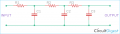
Referring to the #35 schematic, why are there Zobel networks on the U4 and U5 outputs?
Also, the PWM square waves on the 8403's L+ and L- outputs are 180 degrees out of phase with each other. This means that as the R7 headset level pot is rotated from pin 1 to pin 3, the audio in the headphones will go from full volume at the CCW end (pin 1), through half volume, to zero volume in the middle when the two phases cancel out), through the other half volume, to full volume at the CW end (pin 3).
ak
Last edited: