Facebook
 Google
 GitHub
 Linkedin
Hello there,
(See attachment)
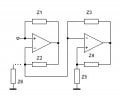
Here is a little challenge. The idea is to simply calculate the input impedance looking into Z1.
This is with all the impedances (Z1, Z2, etc.) made into a pure resistance with value equal to the subscript.
So Z1=1 Ohm, Z2=2 Ohms, Z3=3 Ohms, Z4=4 Ohms, Z5=5 Ohms.
Hint:
Zin (which is actually Rin with all resistors) is either equal to 8/15 Ohms or 15/8 Ohms. Or am i wrong?
Warning: This might be more difficult than it looks like at first glance.
(See attachment)
Here is a little challenge. The idea is to simply calculate the input impedance looking into Z1.
This is with all the impedances (Z1, Z2, etc.) made into a pure resistance with value equal to the subscript.
So Z1=1 Ohm, Z2=2 Ohms, Z3=3 Ohms, Z4=4 Ohms, Z5=5 Ohms.
Hint:
Zin (which is actually Rin with all resistors) is either equal to 8/15 Ohms or 15/8 Ohms. Or am i wrong?
Warning: This might be more difficult than it looks like at first glance.
Attachments
-
 18.4 KB Views: 78
")