Your question is missing a *lot* of information, such as what it is you are trying to do.
Assuming you are trying to use a speaker as a dynamic microphone, that connection will not do anything, because there is no GND reference for the speaker output voltage. Current from the speaker will circulate through both resistors, but the impedance at the connector node with respect to GND is infinite.
thank you for your reply.
the input is actually an 8 ohm speaker output from an amp. the output would go to a different amp's "AUX" input which expects "line level."
thank you for your reply.
the input is actually an 8 ohm speaker output from an amp. the output would go to a different amp's "AUX" input which expects "line level."
Many times, with modern audio circuits, the speaker output pins are both 'floating' (there is NO ground referenced pin) with respect to signal ground for a line level" input or circuit.
You need a LOC (Line Output Converter) for a proper connection.
The most simple way is to keep your circuit, but add a GND connection to the left side of R2 and the speaker lower terminal. This will form a 10:1 divider, with an output impedance of 387 ohms.
BUT as the spook points out, there will not be any GND isolation between the amp output and the AUX input, and this can cause smoke in either or both devices.
Many times, with modern audio circuits, the speaker output pins are both 'floating' (there is NO ground referenced pin) with respect to signal ground for a line level" input or circuit.
The most simple way is to keep your circuit, but add a GND connection to the left side of R2 and the speaker lower terminal. This will form a 10:1 divider, with an output impedance of 387 ohms.
BUT as the spook points out, there will not be any GND isolation between the amp output and the AUX input, and this can cause smoke.
Make that *really* expensive. Anything on that list with a low frequency range below 100 Hz is $$$.
Instead of a transformer you could use two capacitors (in addition to the resistive divider). 4 x 47 uF, configured as two pairs of back-to-back 23 uF caps. With the resistive divider balanced and scaled for a 1 K load, that yields a 14 Hz corner frequency. Note that the GND of the downstream device is not connected directly to either the GND or any output of the source device.
Make that *really* expensive. Anything on that list with a low frequency range below 100 Hz is $$$.
Instead of a transformer you could use two capacitors (in addition to the resistive divider). 4 x 47 uF, configured as two pairs of back-to-back 23 uF caps. With the resistive divider balanced and scaled for a 1 K load, that yields a 14 Hz corner frequency.
The OP could tinker with circuits that could work or spend $25 (including shipping) and get something that solves the problem. The non-Isolated Russound LOC he listed was $40, a total ripoff.
Make that *really* expensive. Anything on that list with a low frequency range below 100 Hz is $$$.
Instead of a transformer you could use two capacitors (in addition to the resistive divider). 4 x 47 uF, configured as two pairs of back-to-back 23 uF caps. With the resistive divider balanced and scaled for a 1 K load, that yields a 14 Hz corner frequency.
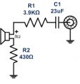
ok, so i can put two 47uFs in series to get a 23. "With the resistive divider balanced and scaled for a 1 K load" This is unclear to me.
I've attached what I think you want me to do. But I doubt it's correct, particularly since I haven't balanced anything. Are you suggesting the use of TWO 47 pairs for L and R channels? Or is the 2nd 23uF cap go to ground?
Would you mind drawing out what it should look like?
The OP could tinker with circuits that could work or spend $25 (including shipping) and get something that solves the problem. The non-Isolated Russound LOC he listed was $40, a total ripoff.
Make that *really* expensive. Anything on that list with a low frequency range below 100 Hz is $$$.
Instead of a transformer you could use two capacitors (in addition to the resistive divider). 4 x 47 uF, configured as two pairs of back-to-back 23 uF caps. With the resistive divider balanced and scaled for a 1 K load, that yields a 14 Hz corner frequency. Note that the GND of the downstream device is not connected directly to either the GND or any output of the source device.
What you have with the capacitors instead of the transformer is a pseudo balanced (the speaker outputs are differential in most modern audio amps) to unbalanced (single ended line input) connection. Common mode signals like hum and noise still have a cable conductor energy circuit path to the line J1 input pin so these types of connections are hit and miss for ground loop noise and hum.
Ground Loops
Almost all cases of noise can be traced directly to ground loops, grounding or lack thereof. It is important to understand the mechanism that causes grounding noise in order to effectively eliminate it. Each component of a sound system produces its own ground internally. This ground is usually called the audio signal ground. Connecting devices together with the interconnecting cables can tie the signal grounds of the two units together in one place through the conductors in the cable. Ground loops occur when the grounds of the two units are also tied together in another place: via the third wire in the line cord, by tying the metal chassis together through the rack rails, etc. These situations create a circuit through which current may flow in a closed "loop" from one unit's ground out to a second unit and back to the first. It is not simply the presence of this current that creates the hum -- it is when this current flows through a unit's audio signal ground that creates the hum. In fact, even without a ground loop, a little noise current always flows through every interconnecting cable (i.e., it is impossible to eliminate these currents entirely). The mere presence of this ground loop current is no cause for alarm if your system uses properly implemented and completely balanced interconnects, which are excellent at rejecting ground loop and other noise currents. Balanced interconnect was developed to be immune to these noise currents, which can never be entirely eliminated. What makes a ground loop current annoying is when the audio signal is affected. Unfortunately, many manufacturers of balanced audio equipment design the internal grounding system improperly, thus creating balanced equipment that is not immune to the cabling's noise currents. This is one reason for the bad reputation sometimes given to balanced interconnect.
A second reason for balanced interconnect's bad reputation comes from those who think connecting unbalanced equipment into "superior" balanced equipment should improve things. Sorry. Balanced interconnect is not compatible with unbalanced. The small physical nature and short cable runs of completely unbalanced systems (home audio) also contain these ground loop noise currents. However, the currents in unbalanced systems never get large enough to affect the audio to the point where it is a nuisance. Mixing balanced and unbalanced equipment, however, is an entirely different story, since balanced and unbalanced interconnect are truly not compatible. The rest of this note shows several recommended implementations for all of these interconnection schemes.
The Next Best Right Way To Do It
The quickest, quietest and most foolproof method to connect balanced and unbalanced is to transformer isolate all unbalanced connections. See Figure 2.
 Facebook
 Google
 GitHub
 Linkedin