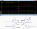
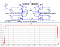
Below is the LTspice simulation of a conceptual design using the PWM scheme to maintain the constant current during the 400μs period.
The PWM (from V6 and V7) generates about 7.5% ripple for the duty-cycle and frequency shown.
You would likely need to monitor the inductor current and use feedback from that to adjust the pulse-widths and duty-cycle to maintain the desired currents.
Below is the LTspice simulation of a conceptual design using the PWM scheme to maintain the constant current during the 400μs period.
The PWM (from V6 and V7) generates about 7.5% ripple for the duty-cycle and frequency shown.
You would likely need to monitor the inductor current and use feedback from that to adjust the pulse-widths and duty-cycle to maintain the desired currents.
Thanks very much
Current feedback measurement is required to monitor the inductor current right? A current sense amplifier maybe ?
And MCU that controls the bridge in PWM mode at high switching chopper frequency ?
Current of V6 compensates losses in R3, R_M2_ON and R_M4_ON.
So V_V6 = I_L1_desired * (R3+ R_M2_ON + R_M4_ON).
V6 changes polarity in time, while HV pulse (7us) lasts.

 Facebook
 Google
 GitHub
 Linkedin