I think one of the problems when this happens is seasoned users working at odds with each other instead of collaborating. When I first started browsing engineering forums, it was very difficult to tell who knew what they are talking about. Many people have ongoing grudges and some constantly try to impress a bunch of people who really don't care about their supposed achievements.
After a few years of this, I have a pretty good idea of who knows their stuff. There are some people I ignore completely because they NEVER provide proofs and somehow think their advice is on par with people who do. I've even had people challenge my proofs without a proof of their own! This generally comes from seasoned "engineers" who seem to think their grey hair trumps all.
With this in mind, I'm trying really hard recently to make my assertions as clear as possible. I've made the effort to provide a verbal description, a schematic and an LTspice simulation as well as follow up to any questions about my work. I'm not saying I'm always right as I'm often wrong but at least you have to disprove my proof before superseding your own! If you aren't willing to do that then you should not be consulting anyone.
Well after hearing all that I have a feeling you are going to be one of the better ones to discuss electronics and related with. It's a pleasure to talk to people that have knowledge yet don't have gigantor egos.
I'm one of the gray haired ones, but I always listen to reason, and I like to go one step farther by encouraging constructive criticism. If I am wrong I want to know about it, and even if you think I am wrong I want to hear about it. I find that I can still learn and I surely can still learn a lot even though I've been involved in this field for well over 50 years.
Here is one of the models I had promised, and I am showing this one because I think it might be my favorite because it describes the leakage inductance as it relates to the coupling factor.
This model is actually easier to use than it might look from the image. It does of course take a little work though because we are dealing with three inductors right off the bat.
This is the T model of a transformer.
A simpler analysis is usually done by just doing an AC analysis. If I get a chance I will show some simple calculations.
Hey everyone
Thank you about the answers!!
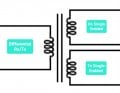
For my finaI project in the university I need a transformer like something in the picture that I attach.
1 or 2 windings in primary and 2 windings in secondary.
I want to work with the transfoemer with continuous sine wave at frequency of 30Khz@3V(P-P).
Max Current(rms):0.4A
ratio: 1:1:1:1
I need something like 1 "input" and 2 "outputs"
I didn't find something that I can buy in the internet
Thank you very much
AT 30 kHZ you can probably get away with an air core transformer, if maximum efficiency is not mandatory. The challenge of "Final Projects is that often you need to explain the design of everything. That is a pain when one does not have all of the formulas available or understood.
I have seen transformers made with the windings, primary and secondary, twisted into a single cable and then wound either on a magnetic core, or many times a non-magnetic core. Depending on the requirements, power level and efficiency, it may be possible to get what you need by making a few prototypes based on a S.W.A.G. Actually, this can provide a workable but non-optimized way to solve some other problem.
Here I was modeling a real pulse transformer from USSR. The number of turns and the core are specified. Three modeling variants - two linear transformers and one nonlinear. Leakage inductances are accounted for in the model.
I went to digikey.com and did a search. digikey pulse transformer
search pulse transformer, greater than 60VuS.
You say 30khz and 3V. For a half sine wave it looks like you will put 3V on the transformer for 1/2 of 30khz so I think you need a transformer that can handle 60VuS.
I don't know current and insulation voltage but here are some options.
Gate Drive Transformer 1:1:1 102volt_uS (100V for 1uS or 50V for 2uS or 25V for 3uS I think you understand) It has about 1 ohm for each winding. The inductance is maybe low for you application. 750uH. I use this transformer!
pulse transformer 1:1:1 500uH 3mH Here is a high inductance transformer. Lower current. This is probably good for sending signals. Start with looking at this one.
Here I was modeling a real pulse transformer from USSR. The number of turns and the core are specified. Three modeling variants - two linear transformers and one nonlinear. Leakage inductances are accounted for in the model.View attachment 309267View attachment 309268
This is something I would really like to know how to do. How were you able to plot the magnetic flux density in LTSpice? I would like to be able to compute B-H curves on LTSpice.
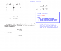
Here is an example of a galvanically isolated voltage source.
To plot the magnetization reversal of the core, it is necessary to plot v(B) and replace the X axis from time -->v(H).
This is something I would really like to know how to do. How were you able to plot the magnetic flux density in LTSpice? I would like to be able to compute B-H curves on LTSpice.
I do not use LT Spice for this but if you care to try check out the sources used for "B" and "H" in that previous reply.
There's a little bit of a trick to it where apparently you have to create your own calculation for B and H before you can graph them and that is done with the two sources (with outputs B and H on the schematic).
Also, because of that little trick, you would have to find out what the scaling factor is for the graph. It's obvious that B and H are not in units of 'volts' also.
Here is an example of a galvanically isolated voltage source.
To plot the magnetization reversal of the core, it is necessary to plot v(B) and replace the X axis from time -->v(H).View attachment 309816
You're a brilliant guy Bordodynov. You seem to be using a subcircuit that I'm not familiar with from your [ZZZ] model library? It looks like it integrates the "core_H_B.asy" subcircuit with transformer turns ratio?
Which models from your [ZZZ] library would you recommend for replicating your provided examples? A .asc file would be great also if that's not too much to ask.
Here is an example of a galvanically isolated voltage source.
To plot the magnetization reversal of the core, it is necessary to plot v(B) and replace the X axis from time -->v(H).View attachment 309816
What we have is no mentions of transformers for sine waves, after the TS mentions the details:
I want to work with the transfoemer with continuous sine wave at frequency of 30Khz@3V(P-P).
Max Current(rms):0.4A
ratio: 1:1:1:1
I need something like 1 "input" and 2 "outputs"
No discussion as to what is requested. All sorts of other information about pulse transformers.
And I forgot to ask about the actual application. With one winding given as "TX" and the other as "RX" it does not seem like a pulse transformer application at all. More like some sort of sonar system. Which I did for a high school science fair project 60 years ago. Not as a university final project.
So there is a lot of information missing. But it is not a power supply transformer or a pulse transformer. That part is fairly obvious based on the posting.
You're a brilliant guy Bordodynov. You seem to be using a subcircuit that I'm not familiar with from your [ZZZ] model library? It looks like it integrates the "core_H_B.asy" subcircuit with transformer turns ratio?
Which models from your [ZZZ] library would you recommend for replicating your provided examples? A .asc file would be great also if that's not too much to ask.
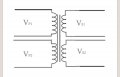
My method for building transformers is simple. A transformer consists of windings and a core. In each winding, the number of turns, ohmic resistance and parasitic capacitance are indicated (there is an option with leakage inductance). The winding and the core have an additional pin. By connecting them together we get a transformer. It's like a magnetic connection.
My method for building transformers is simple. A transformer consists of windings and a core. In each winding, the number of turns, ohmic resistance and parasitic capacitance are indicated (there is an option with leakage inductance). The winding and the core have an additional pin. By connecting them together we get a transformer. It's like a magnetic connection.View attachment 309988View attachment 310012
What we have is no mentions of transformers for sine waves, after the TS mentions the details:
I want to work with the transfoemer with continuous sine wave at frequency of 30Khz@3V(P-P).
Max Current(rms):0.4A
ratio: 1:1:1:1
I need something like 1 "input" and 2 "outputs"
No discussion as to what is requested. All sorts of other information about pulse transformers.
And I forgot to ask about the actual application. With one winding given as "TX" and the other as "RX" it does not seem like a pulse transformer application at all. More like some sort of sonar system. Which I did for a high school science fair project 60 years ago. Not as a university final project.
So there is a lot of information missing. But it is not a power supply transformer or a pulse transformer. That part is fairly obvious based on the posting.
Hey
is not all my project, is small part from my Total project. My total project is a Health sensor and part of the project I use FSK moudulation to communicate.
I just looking for transformer of 1:1:1:1 that can work about 30KHz.
Thank you
Hey
is not all my project, is small part from my Total project. My total project is a Health sensor and part of the project I use FSK moudulation to communicate.
I just looking for transformer of 1:1:1:1 that can work about 30KHz.
Thank you
 Facebook
 Google
 GitHub
 Linkedin
")