 Facebook
 Google
 GitHub
 Linkedin
Hello all.
Can anyone tell me how this works please?
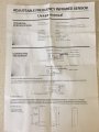
Please see pic.
Obviously the red and black is power to the sensor but when the sensor is activated, how does it become an active circuit or switch?
Can anyone tell me how this works please?
Please see pic.
Obviously the red and black is power to the sensor but when the sensor is activated, how does it become an active circuit or switch?
Attachments
-
 187.2 KB Views: 37
 -
 179.5 KB Views: 20


