How does OP-AMP in voltage regulator works?

Thread Starter

Dong-gyu Jang

Joined Jun 26, 2015
115
Hello.

I've now studied concept and basic principle of electronic voltage regulator.

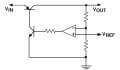
You better see the attached image first.

The OP-AMP here should be brain of voltage regulator as it determines whether output voltage of the regulator matches to target voltage (The output voltage corresponding V_ref in voltage divider) or not. Question is how it control current.

I've attempted to trace voltage drop and I'm so easily stuck right now. When two inputs of OP-AMP are matched then...what is the output voltage? And when it is not matched, How OP-AMP controls current through transistors to match output voltage to target voltage?

Maybe I still don't have good mind in use of OP-AMP.
 

Attachments

wayneh

Joined Sep 9, 2010
17,498
The op-amp in that circuit operates at maximum gain so you might say it is arranged as a comparator that will swing from "on" to "off" over a very narrow voltage range - a few millivolts at most. This will cause the output voltage to be held in that narrow range where the transistor is conducting just enough to drop Vin down to Vout, where the voltage on the op-amp's input pins is nearly equal. The op-amp will be in linear operation in this mode - with an output voltage just enough to hold the transistor "on" just enough.

This arrangement won't work unless Vin can be drawn down by a little current through the transistor. A beefy supply would just cook the transistor.
 
Last edited:

dl324

Joined Mar 30, 2015
16,922
Maybe if you think of the opamp as being configured as a voltage follower it would be easier to understand.

Assume the resistors in the voltage divider are the same value so the voltage applied to the non-inverting input will be 1/2 of the desired output voltage. If you apply say 4V to the non-inverting input, the opamp will try to make it's output voltage whatever it needs to be to make the voltage on the inverting input the same as the non-inverting input. To do that, it will apply increasing voltage to the base of the NPN transistor, turning it on which will turn on the PNP transistor. It will increase the drive to the NPN until the output is 8V.

BTW, the base resistor isn't required in this application.
 
Last edited:

AnalogKid

Joined Aug 1, 2013
11,044
Question is how it control current.
It doesn't. Your circuit is a voltage regulator only. This circuit will attempt to pass through whatever current the external load wants to draw. If the current is too high for the PNP pass transistor or if the power dissipated by the pass transistor is too high, it will fail. The current through the regulator is controlled only by the impedance and actions of the circuits or devices connected to it.

ak
 

crutschow

Joined Mar 14, 2008
34,452
...................
When two inputs of OP-AMP are matched then...what is the output voltage? And when it is not matched, How OP-AMP controls current through transistors to match output voltage to target voltage?
...................
When op amps are operating in a linear mode with negative feedback then there is always a small voltage difference between the inputs.
This voltage is equal to the output signal of the op amp divided by the open loop gain so it is very small for the typical large value of gain that most op amps have.
When the op amp is operating linearly it adjusts the output voltage such that the negative feedback maintains the small required difference voltage between the op amp inputs. Since this voltage is so small it is often considered to be zero when calculating the feedback voltages and currents to simplify the calculations.
 

Thread Starter

Dong-gyu Jang

Joined Jun 26, 2015
115
Maybe if you think of the opamp as being configured as a voltage follower it would be easier to understand.

Assume the resistors in the voltage divider are the same value so the voltage applied to the non-inverting input will be 1/2 of the desired output voltage. If you apply say 4V to the non-inverting input, the opamp will try to make it's output voltage whatever it needs to be to make the voltage on the inverting input the same as the non-inverting input. To do that, it will apply increasing voltage to the base of the NPN transistor, turning it on which will turn on the PNP transistor. It will increase the drive to the NPN until the output is 8V.

BTW, the base resistor isn't required in this application.
Thanks for comments everyone! And I would like ask a little more question for this issue.

Okay. I got a feeling that OP-AMP eventually controls transistor current (from emitter to collector in upper PNP transistor) to regulate current through the load of the voltage regulator. In this sense, why does OP-AMP not directly control PNP transistor via direct contact of its output to base of the transistor? Why OP-AMP -> NPN transistor -> PNP transistor? instead of OP-AMP -> PNP transistor simply? I guess this "Darlington"-like transistor pair has advantage of much more dynamic range of current control compared to single transistor?
 

AnalogKid

Joined Aug 1, 2013
11,044
The npn driver for hthe pass transistor has two possible advantages. First, many opamp output stages can not drive the output all the way up the the opamp positive supply voltage. If the opamp is powered from the same bulk DC supply that is being regulated, the opamp might not be able to turn down the output voltage.

Second, the opamp might be separately powered, so that it can regulate a voltage much greater than it's own max voltage. The drive transistor could be rated for huncreds of volts and act as a voltage translator as much as an amplifier.

ak
 
Top