How do you validate a new SMT placement program before running the first board?

Thread Starter

KayZhao

Joined Aug 18, 2026
15
I work as a software engineer at ETON, an SMT equipment manufacturer. I am interested in how different factories verify a new placement program before releasing it to production.

CAD and BOM data may look correct on screen, but the first run can still reveal problems such as a wrong board origin, incorrect component rotation, mismatched package data, or the wrong feeder and nozzle assignment.

The basic workflow I have in mind is:

  • Confirm the PCB, BOM and centroid file revisions
  • Check units, board origin and panel orientation
  • Review pin 1 and polarity for ICs, diodes and electrolytic capacitors
  • Verify package, feeder and nozzle assignments
  • Perform a slow or dry run
  • Inspect the first assembled board before releasing the program
  • Save the approved program as a controlled revision
For people who set up or maintain SMT lines, which of these checks catches the most real-world mistakes?

Do you rely mainly on offline simulation and preview, or do you always require a physical first-article build? I would also be interested to know which checks you wish the machine software could perform automatically.
 

MisterBill2

Joined Jan 23, 2018
28,231
Since the PCB that receives the parts must already be designed, and verified, placing parts on an actual board is the last check.
Consider that not only the placing must be verified, but also every bit of the fixturing needs to be verified for accuracy.
Prior to that, the coordinates of every part position need to be verified, and the accuracy of the specific machine must be checked.
Pictures on a screen look nice, but they are seldom "close enough."
 

Thread Starter

KayZhao

Joined Aug 18, 2026
15
Since the PCB that receives the parts must already be designed, and verified, placing parts on an actual board is the last check.
Consider that not only the placing must be verified, but also every bit of the fixturing needs to be verified for accuracy.
Prior to that, the coordinates of every part position need to be verified, and the accuracy of the specific machine must be checked.
Pictures on a screen look nice, but they are seldom "close enough."
That is a good point. I was mainly thinking of the first board as a check of the placement program, but it also verifies the physical setup: the board support, clamps or conveyor, fiducial recognition, tooling and the machine itself.

It probably makes sense to separate the process into three stages: check the input data first, verify the machine and fixturing setup, and then use the physical first article as the final acceptance check. An offline preview can find obvious coordinate or rotation errors, but it cannot prove where the machine will actually place the component.

Would you normally check the machine accuracy with a calibration board before a new-product run, or is that usually confirmed as part of the first-article inspection?
 

panic mode

Joined Oct 10, 2011
5,240
sounds like you are looking to implement something similar to JLC PCBA ordering wizard and used in on production floor.

as a user, i do my best to doublecheck all parts orientation when submitting PCBA order. still - import of data tends to break down from time to time.
one example for sure is part orientation....

i had board with two DPACKs (same part numbers) sitting parallel next to each other, centroid says the orientation is the same just Y position value is different, yet upon import, one was ok and the other was turned 90deg.
i was trying to see what exactly causes it so i was deliberately restarting order process / submitting same centroid file and only changing rotation of single part to 0, 90, 180, 270 deg,
and most of the times, part would indeed be rendered in 4 distinct orientations as expected. sometimes however, more than one import (with different rotation value) was either rendered in same orientation, or instead of expected 90deg increment, it was 180deg from expected.
another thing that came up (and now is a standard check for certain parts) is reflow temperature... in case of JLC, Standard and Economy process assembly have different temperatures. Economy is higher by few degrees. QC team noticed deformation of some Omron signal relays.
the outer walls are normally flat but if heat is above some value they start to shrink. Function was not impeded but from that point, if such parts appear in BOM, Standard assembly is forced.

placement also need sufficient room around the part so that pick and place tools can hold and move parts into position without colliding with other parts. many problems can be avoided with properly setup DRC rules. similarly, messed up or not used DRC can introduce many issues.
copper areas pull back, texts on bottom layers (Cu, Silk...) need to be "backwards" to be readable when viewed from the bottom. subtract layers so that silkscreen for example does not appear across pads etc.
how much you want to check is up to you but i can see this becoming an ongoing effort.
 
Last edited:

Thread Starter

KayZhao

Joined Aug 18, 2026
15
sounds like you are looking to implement something similar to JLC PCBA ordering wizard and used in on production floor.

as a user, i do my best to doublecheck all parts orientation when submitting PCBA order. still - import of data tends to break down from time to time.
one example for sure is part orientation....

i had board with two DPACKs (same part numbers) sitting parallel next to each other, centroid says the orientation is the same just Y position value is different, yet upon import, one was ok and the other was turned 90deg.
i was trying to see what exactly causes it so i was deliberately restarting order process / submitting same centroid file and only changing rotation of single part to 0, 90, 180, 270 deg,
and most of the times, part would indeed be rendered in 4 distinct orientations as expected. sometimes however, more than one import (with different rotation value) was either rendered in same orientation, or instead of expected 90deg increment, part would render after import as 180deg.
another thing that came up (and now is a standard check for certain parts) is reflow temperature... in case of JLC, Standard and Economy process assembly have different temperatures. Economy is higher by few degrees. QC team noticed deformation of some Omron signal relays.
the outer walls are normally flat but if heat is above some value they start to shrink. Function was not impeded but from that point, if such parts appear in BOM, Standard assembly is forced.

placement also need sufficient room around the part so that pick and place tools can hold and move parts into position without colliding with other parts. many problems can be avoided with properly setup DRC rules. similarly, messed up or not used DRC can introduce many issues.
copper areas pull back, texts on bottom layers (Cu, Silk...) need to be "backwards" to be readable when viewed from the bottom. subtract layers so that silkscreen for example does not appear across pads etc.
how much you want to check is up to you but i can see this becoming an ongoing effort.
Thanks, this is exactly the kind of real example I was hoping to hear about.

The two identical DPAKs ending up with different orientations is especially interesting. If the centroid values were correct, it suggests that the import or package mapping can introduce errors that are not obvious from checking the source file alone. So the rendered result still needs to be checked part by part, especially for polarized or asymmetric components.

I had not considered reflow-temperature restrictions as part of program validation, but your relay example makes a good case for linking process limits to specific part numbers.

I agree that checking everything could easily become an ongoing project. I would probably start with the most common and costly problems: orientation, package mapping, placement clearance and temperature-sensitive parts.

Did you notice the DPAK error in the ordering preview, or only after the boards were assembled?
 

panic mode

Joined Oct 10, 2011
5,240
first of all i would really like to say that JLC is doing tremendous job. they are very professional and responsive. they will do their best to catch anything suspicious and communicate with user any concern.

i catch and correct placement/orientation during order placement because i am OCD and alway make sure that everything is clear.

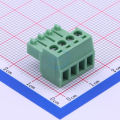
for example one of the issues is that JLC parts website has plenty of pluggable terminal blocks to choose from. And many look exactly the same but - have pinout reversed.
to avoid potential problems, i not only check 3D renderings to confirm orientation, i also make custom footprints with silkscreen clearly showing mechanica shape/coding.
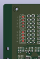
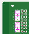
also since i normally order them fully assembled (with plugs), i use matching index for header (J1,J2,J3...) and plugs (P1,P2,P3...) and make sure both identifier are next to each other on the silkscreen:

1789735906599.png
1789736422674.png

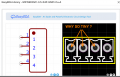
when making my footprints i always check JLC footprints as well. two problems here: they really make the pin numbers VERY small.
also they do not show dimensions or even origin. the 0.1" (2.54mm) grid is the only guide. for numeric values i always refer to datasheet anyway.


1789737081931.png

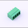
also while pluggable terminals look identical (4P, 3.5mm pitch in this case), they are not...! Asian manufacturers make subtle changes that make mixing brands a problem:
1789736700529.png1789736612786.png

So pick one brand and stick with it because in many cases they are not compatible. Avoid temptation to mix them up because stock levels may not be what you would like.
if not sure, DNP them for PCBA and order them separately elsewhere. It is possible to aggregate the LCSC and JLC orders so that you do not pay separate shipping (check with LCSC for details, JLC does not mention this).
 
Last edited:
Top