hi tru,
That doesn't sound correct.?
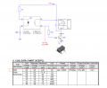
For reference only, this image is a circuit of my 5V relay PCB. normally the relay is energised when the Input is pulled Low.
Using my PIR 3v out signal connected to the Base drive resistor, as shown in RED, I can operate the relay with the PIR output signal.
[Don't connect the normal relay Input signal].
Identify the Base resistor [it will be a different resistance value to my 5v relay PCB] and connect a TEST 3v wire to the end of the Base resistor, the relay should operate.
My circuit will show you where to connect the TEST wire.
If the relay operates you can connect the output of the PIR to the TEST wire.
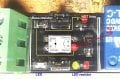
Again thanks for your efforts and time. I believe I tested as you explained. See image.
FYI... I used one power source to power both PIR and Relay. Used a 5v power supply.
The image shows 4 contact points where the relay triggered from the PIR output signal by making contact with the TEST wire.
The RED points gave a strong trigger, while the YELLOW point gave a weaker trigger effect, but the relay did trigger.
So... is your recommendation to solder a wire to one of these points then connect the PIR output signal to that wire? Which point would you recommend?
Also, what is the function/additional purpose of these jumpers on the PCB? All I know is that if you remove a jumper it kills the circuit to the relay.
hi tru,
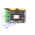
Check this modified image of your PCB.
Do NOT connect directly to the transistor BASE, this could damage the transistor.
Connect the TEST wire to pin 3, [ emitter of the opto] .
I have marked in Yellow the most likely connection between pin 3 and the transistor Base drive resistor.
This appears to be same as my double relay PCB.
Note: the yellow line does not represent the actual copper track.
The Base resistor is coded 101, which means 100 ohms.
The 102 resistor, is for the LED is 1000 ohms.
With ref to the jumpers I would be guessing as I cannot see the PCB copper track on your image.
A single jumper link on my PCB selects either the PCB's +Vsupply to th opto collector or leaves the opto collector open circuit.???
If I place the jumper in its second position it shorts out the +Vcc to 0v.!!!!!!
Thanks again. I will go with the connection to the opto and see how things run. I guess at worst i fry a PIR and/or relay. Overall not a big loss. $2 for the PIR. Ended up getting refunded for the 5 relays with no request to send back to China. On the plus side, learned quite a bit from your guidance. And another case where you get what you pay for, 5 relays cheap. May even unsolder a relay and try my own module in the future. Plan on continuing on with the level shifting circuit as a solution as well.
hi tru,
The combination of only 3 terminals on the Input connector block and only 2 jumper links means that by inserting or removing the jumpers, you would still have to add a wire to supply 3v to the opto-output/transistor/relay.
The 3v connected to the above opto/trans/relay would not be isolated by action of the opto isolator
With the PIR connected to the Base, the only isolation between the high voltage and the PIR and the 3v supply are the relay contacts/terminal block.
Checking the relay datasheet shows that the relay is designed to switch up to 250Vac and has a 500Vdc rating.
Many industrial applications rely solely on the isolation provided by the relay contacts.
Thanks Eric. Apprciate all your help with this. Learned lots along the way. Would be great if someone could develop a working 3v module and get it on the market. From my searches it appears there is only one manufacturer producing this concept from Asia.
hi tru,
If you would like to investigate this problem a little further, will you please measere the 6 voltages marked A, B,C, D, E,F relative to the Gnd pin.?
Apply +5v to the Inp terminal while measuring the voltages, keep the jumper links in place.
hi tru,
If you would like to investigate this problem a little further, will you please measere the 6 voltages marked A, B,C, D, E,F relative to the Gnd pin.?
Apply +5v to the Inp terminal while measuring the voltages, keep the jumper links in place.
hi tru,
If your PCB Input circuit is similar to my PCB.
ie: with the 1000R , Opto emitter and LED in series from the Inp to Gnd, its possible by reducing the value of the 1000R or shorting out the LED to make the Inp circuit accept a 3v control signal.
From your measured voltages, I can determine if a simple change will be OK for 3v.
hi tru,
If you would like to investigate this problem a little further, will you please measere the 6 voltages marked A, B,C, D, E,F relative to the Gnd pin.?
Apply +5v to the Inp terminal while measuring the voltages, keep the jumper links in place.
tru,
Apply +5v to the VCO terminal and 0v to the Gnd terminal, this should turn On the LED, then do the requested measurements.
The In terminal can be left disconnected.
The negative lead of the meter will always be connected to 0v while doing the checks, you will then place the meter positive lead on each of the A... F points.
E
NOTE:
The terminal block letter coding is not well defined.
ie: VCO I believe means Voltage control and In means +V.???
Applying +5v to either VCO or IN will not damage the PCB, apply the +5v to the terminal that lights the LED
Hope this image makes things more clear as to how to get the LED indicator to light and do measurements. If I switch +5v to VCC and leave nothing in the Input then the LED will not light.
VCC: No connection
Input: +5v (this is where the 3v input signal from PIR would be connected if source voltage were connected to the VCC)
GND: 0V
When taking measurements, -Black meter lead was always on GND terminal. +Red meter lead was use to touch measurement points.
Measurements has you asked for.
A 0v
B 2.1v
C -4.8v
D -4.8v
E 3.3v
F 2.1v
hi,
From your measurements, I would say this image is close to your PCB circuit.
As you can see the Opto emitter has a forward voltage drop of 1.2v which is in series with the LED, which has voltage drop of 2.1V.
That's a total of 3.3v, add to that any drop across the 100R and it's clear that the circuit could not operate the relay, with a3v Inp signal.
When the Inp is 5v the opto circuit draws approx 17mA, which is typical.
The only way to make that PCB accept a 3v Inp signal, would be to short out the LED.
The problem is that the PIR cannot output 17mA at 3v.
My PIR seems to limit at around 1.2mA.
E
Note : For Ref only, in my Post #51 the 100R and 1000R are marked incorrectly.
The 1000R is in the Base of the transistor.
 Facebook
 Google
 GitHub
 Linkedin