How do I know what this transistor is?

Thread Starter

tbfunk

Joined Dec 9, 2010
30
I have been combing through every peice of literature I can find including alot of videos and articles and I am pretty sure I understand how a transistor works, however I am quickly realizing I dont.
Its also really hard to find datasheets on some older transistors so I was wondering if there is a way to test the transistor to make sure its a switching npn? (which is what I need)
Also is there a way to tell simply by looking at the markings?
EX. I have a transistor with the text:
PJ733
P
1C1 P
What does this tell me? (pnp?)
 

thatoneguy

Joined Feb 19, 2009
6,359
Do you have a photo with high enough resolution to make out all of the markings?

The only one I've found close to your info is a surface mount MOSFET.
 

SgtWookie

Joined Jul 17, 2007
22,230
Many manufacturers use "house marked" components that don't cross-reference to commercially available parts.

You can figure out whether it is a PNP or NPN transistor by using a diode tester. Many multimeters (even very inexpensive ones) have a diode test function.

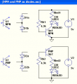
Here are NPN and PNP transistors, what they look like to a diode tester, and how to use them as a saturated switch:


The diode tester will help you figure out which lead is the base, and whether the base-emitter and base-collector junctions are good (not open nor shorted). The diode tester should read between 0.6v and 0.75v when the junction is forward biased.

Once you determine the transistors' type (NPN or PNP), then try it in the appropriate LED driver circuit to the right.
You can't determine which is the collector or emitter with a diode tester, so you may have to swap the other two leads around.
With a 5v supply, the 4.3k base resistor will allow 1mA base current, and the 330 Ohm Rled will allow 10mA current to flow through a red LED that has a Vf of 1.7v.

If you don't have a diode tester, you could use a 5v supply, a red LED, and a 330 Ohm resistor as a current limiter to figure out which is the base.

The use of 4v to 5.5v is suggested, as higher voltages may exceed the breakdown voltage of the transistor.
 

Attachments

Last edited:

Thread Starter

tbfunk

Joined Dec 9, 2010
30
Thanks so much SgtWookie!

Also one more question guys.

Can I use ANY transistor as a switch (or amplifier?) or do some transistors do other things than switch?

I heard somewhere most mosfets work great as switching transistors
 

shortbus

Joined Sep 30, 2009
10,049
Sgt. - Dumb question time :) Is it possible to use a transistor base/emitter or base/collector junction in place of a diode? Thank you.
 

tyblu

Joined Nov 29, 2010
199
Short answer: no, you can't use any transistor as a switch. You need to match its electrical characteristics to the load you will be switching. For example, you can't use a 100mA device to turn on a 1A load. Elsewhere, a 100A power BJT won't work as a logic switch due to its high base and leakage current and voltage. These are extreme examples, but you get the idea.
 

R!f@@

Joined Apr 2, 2009
10,014
@shortbus.....
Are you trying to pull Sgt leg..

You know he has a big gun and a sword too. If I were you I would keep my distance from Sgt.
 

shortbus

Joined Sep 30, 2009
10,049
R!f@@ - No this was a real question, seems that I read that some where. The post he made about testing with a diode tester made me remember it. So your say it won't work?

Sgt. has answered many of my questions and explained where my thinking was wrong. I have the utmost respect for him.
 

Thread Starter

tbfunk

Joined Dec 9, 2010
30
Thank you R!f@@ for the numbers/codes!
How did you find those?

Also tyblu would you mind clarifying? When I asked if you could use any transistor as a switch I was assuming the conditions were suitable for said transistor. I just want to know if EVERY transistor does essentially the same switching/amplifying thing some of the ones I know about do.

My whole goal from this is to completely understand how the transistor works and be able to figure out from there how to combine them to do what I want. Essentially to have a better understanding of how chips work and how I might be able to make my own or add on to existing ones.

It seems like any explanation on the internet assumes that you know that transistors switch and I wanted to clarify.
 

tyblu

Joined Nov 29, 2010
199
yes, every transistor has the possibility of switching. There are essentially 3 modes of operation for a transistor (explanation for N-channel/NPN FET/BJT): OFF, when there isn't enough potential/current between the gate/base and source/emitter to make the channel* conductive; ON, when the aforementioned potential/current is more than enough to make the channel* as conductive as it will ever be; and LINEAR, when that Vgs/Vbe is somewhere between ON and OFF -- any changes to this voltage affect the channel* conductivity drastically, which can be used to amplify signals. Other than this, it's good to know that current doesn't flow well backwards, from source/emitter to drain/collector -- that's why there are two types: N-channel/NPN and P-channel/PNP, complimentary transistor types. You can see them used together in CMOS (complimentary MOS) circuits, push-pull circuits (AB-amp), and to drive** each other. Wikipedia will tell you about more regions of operation and other details. The Art of Electronics has many fairly advanced example circuits.

*By "channel" I mean the space between the drain/collector and source/emitter. This is the region whose conductivity is modulated by voltage/current.
**To "drive" a transistor means to input voltage/current into its gate/base, and is typically used for FETs with either unusually high input capacitance (think slow RC and current spikes) or high turn-on voltage, or used for BJTs with either the same turn-on voltage issue or more base ("injected") current than is available from the signal side.
 

SgtWookie

Joined Jul 17, 2007
22,230
Sgt. - Dumb question time :) Is it possible to use a transistor base/emitter or base/collector junction in place of a diode? Thank you.
It's not a dumb question.

You can "sort of" use a transistor as a pair of diodes, if you're dealing with low voltages. The base-emitter junction of many common transistors will break down if subjected to more than ~6v reverse. If the current is not limited, the BE junction will be destroyed.

Some "white noise" generator circuits use a BE junction biased in reverse as a noise source; the collector is left open (disconnected).

The base-collector junction can usually withstand a much higher reverse voltage. So, if a transistor has a shorted or open BE junction, you might still use the BC junction as a diode.
 

tyblu

Joined Nov 29, 2010
199
The "body diode" is used in power FETs. You'll have to look it up as I know little about it, other than this junction exists to eliminate a pseudo-transistor effect at high currents (the diode you see in power transistor schematic symbols is the body diode).
 

Thread Starter

tbfunk

Joined Dec 9, 2010
30
Thank you so much tyblu! Exactly what I wanted to know! :D

I now have another question... What am I doing wrong??

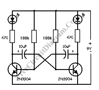
I have known the simple led flasher circuit for a while but Ill use this schematic as a refrence since I am horrible at drawing:

The only thing that differs on my circuit are the transistors, of which I know now are NPN. However when I hook up the circuit to test on my breadboard the leds dont flash they are both constantly on.

And while typing this I realized I didnt try to figure out if they were flashing faster than I can see, however assuming they are not is it possible my transistors are broken? or would a fried transistor not conduct any electricity at all?

Another thing I am having a little trouble with is since a PNP is the inverse of an NPN, if I hook it up correctly, changing only where the base/emitter/collector of the transistor are connected in the circuit, would I be able to effectively replace an NPN with a PNP?


Is A not essentially the same as B?
 

tyblu

Joined Nov 29, 2010
199
A and B are not the same because...
tyblu said:
current doesn't flow well backwards, from source/emitter to drain/collector -- that's why there are two types
Transistors aren't made symmetrically (look at the WikiP picture), so they have different forward and reverse current gain, known as \(\beta_{F}\) and \(\beta_R\). One is usually only interested in \(\beta_F\).

Your circuit doesn't work with random transistors because it is highly dependent on specific characteristics of the originals. I want to call it an astable multivibrator, but I'm not sure -- the diodes makes it appear to be more sequential (RC delay) than resonant, though I 'suppose there is little difference. I bet the ebook on this site describes one.
 

shortbus

Joined Sep 30, 2009
10,049
It's not a dumb question.

You can "sort of" use a transistor as a pair of diodes, if you're dealing with low voltages. The base-emitter junction of many common transistors will break down if subjected to more than ~6v reverse. If the current is not limited, the BE junction will be destroyed.

Some "white noise" generator circuits use a BE junction biased in reverse as a noise source; the collector is left open (disconnected).

The base-collector junction can usually withstand a much higher reverse voltage. So, if a transistor has a shorted or open BE junction, you might still use the BC junction as a diode.
Sgt. - Thank you for your answer!
 

Thread Starter

tbfunk

Joined Dec 9, 2010
30
Thank you all so very much!

Yea I figured using random transistors would probably be futile, while its easy to grab resistors and caps from useless electronics (im using old vcrs and receivers :p) I guess I HAVE to buy my transistors.

I went out and bought a bunch of 2n2222's and hopefully they work.

I just wish there was more documentation on recovering old parts and reusing them, or at least have some markings like how a resistor has the bands and caps have the voltage limit and farads written right on them (for the most part).

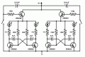
Which brings me to my final question because I am having trouble with a project I told a friend I would figure out. Attached is my schematic so far.

Some polarities might be wrong and any advice is greatly welcomed!
Essentially I am trying to acheive a timed blinker circuit for roughly 5 seconds once one of the buttons are pushed. I know my schematic probably wont work so go easy :p
 

Attachments

Top