Facebook
 Google
 GitHub
 Linkedin
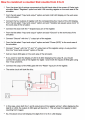
Hello! I'm trying to design a circuit that counts from 0-9 using CEDAR Logic Simulator.
I have followed the exact same steps in my textbook, but for some reason my circuit only displays 1,4,7 repeatedly and then displays 8.
Then it displays 2,6 repeatedly then displays 9.
I would like it to count 0,1,2,3,4,5,6,7,8,9 and then start over again.
Any help is greatly appreciated!
I have followed the exact same steps in my textbook, but for some reason my circuit only displays 1,4,7 repeatedly and then displays 8.
Then it displays 2,6 repeatedly then displays 9.
I would like it to count 0,1,2,3,4,5,6,7,8,9 and then start over again.
Any help is greatly appreciated!
Attachments
-
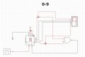 84.6 KB Views: 33
 )
)