There have been others that have used a similar circuit for PWM input controllers.
You need to do a little more checking as to the terminal strip, does the VDD and +15v have any voltage on them? IOW is this supplied on board or fed externally?
Also the other side of the diode input to the opto you mentioned, see if this comes out to the outside terminal.
Without having the board in hand it is difficult to do this at a distance.
Max.
I get a 50kohm connection from the +15v/VOD pin next to the PWM pin to the anode of the optocoupler. And that is the only pin I get any reading on. And when i have the board powered on I get a 16.3vdc reading on that same pin!
I got way ahead of myself, in between the pins and the optocoupler is a 74HC14D quad 2 input nor gate and then a PIC16F73 28 pin chip. Looking at the data sheets on both of these has got me thinking it will be next to impossible for me to figure this out by hooking in to the pin header. Do you think its possible for me to maybe bypass all of that and tie in right to the optocoupler somehow?
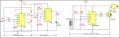
You can try this with a little modification I found on the internet. This drawing is for DC Motor and you can replace the TIP122 with a transistor and connected to your optocoupler. I hope this works. Have it a try and give us a feedback.
Hi All, simply put...NO....there is no way to operate this control board from a simple pot. This controller requires a pwm input and valid feedback from a front roller and the motor encoder attached to the controller.
BTW, you also have bad capacitors on this board!! DO NOT use this board as is or it absolutely will result in smoke at a higher load with those 3 degraded storage caps on that board, which are 560uf 200v, and available thru digikey. The pinout information is there for the controllers, but there is a lot of "thinking" to do to make this work from scratch. I don't have schematics for this but designed a few of the circuits used on it, during my time at Johnson, the parent to Horizon fitness.
Google TREADMILL ANALYZER for a device similar to what you are looking for ....good luck!
The reed switch would be easy, figure the relationship between the roller rotating speed, and motor rotating speed and make an idler shaft to replicate said relationship, simple machining job.
Is there anything else that is required to make this controller work the motor OUTSIDE of the treadmill.
Hi All.... Well, I must say I am glad to hear of the PWM drive for speed control. When folks want to simply add a pot to control speeds, they should understand the meaning of hot-grounded drive circuits and see why it's a bad idea to try the pot added to a point inside this hot-grounded drive circuit. Most controllers run these hot grounds, which requires the opto-isolators for passing speed and fault commands to and from the hot side to the common grounded or cold side on most controllers made by DCI for many fitness manufacturers.
This particular controller is the part SJED08089IF or Horizon part number 032669if with a list cost of $220.
The display provides the speed command at a specific frequency, and that duty-cycle is allowed to adjust from 0-90% on time. This is conditioned coming into the controller and passed to the PIC chip. The PIC chip watches the incoming pwm and uses this to set-up the main switching frequency of that main FET that switches the +Vbulk motor voltage that Max mentioned earlier in this thread, which does indeed sit at a hefty +165vdc referencing its hot-ground that you do not want to attach your o-scope lead to, or a meter if you don't know where the grounds reside, of which there are "3" separate grounds on this controller, beware of this note!!
You cannot cross grounds from one circuit to another, or serious troubles will arise.
There are no schematics for this unit, only in my head from years ago when I had the only copy I knew of hanging above my desk on the wall as we designed new units and sustained this after launch.
You can read the pinouts but I must stress the hot-ground issue, read up on it if you're unsure, and be sure to check all Johnson motors for leakage resistance to frame ground, as they should have a grounded shaft, the tiny tab is at the rear of the shaft hidden under that encoder when it is in place in the tread. This keeps the shaft from floating, and the windings are wound around the shaft with ends at the commutator.
This board also needs an "enable" logic signal to allow the pic to send the hi-speed switching pwm to the hot-grounded motor drive circuits. The PIC also needs the encoder feedback which is the 5-pin and notice pin-5 is the shield, which doesn't even get attached inside the sensor, or board if I remember right, hahahahaa......
This encoder spins at shaft speed, and will saw things in two, so it was always called the wheel of death at Horizon, it will hurt you, keep very clear or guard this. The remaining 4-wires are power, a ground-pair and a return pulse from a split-opto that watches the 177 slotted grooves pass thru the sensor. This provides a return feedback pulse-train of many Khz depending on selected speed. This return signal must match a stored "library" of acceptable returns per incoming PWM setting, clever.
The PIC also needs the returning front roller sensor that was required back then, to watch for a moving walking belt, via that front roller and a small magnet in the pulley. This is where the mechanical folks take over, with the diameter from the center of the roller shaft to the set position of the magnet hole, and the mating drive pulley on the motor shaft results in the front roller frequency returning to that PIC chip, which also watches this feedback for a mis-match when compared to the master PWM coming in, and the returning hi-speed encoder feedback. Clever again.
That one LED lights when the main motor power rail energizes, via the safety relay-set, one allows inrush limiting, and the main relay switches the pre-charge circuit completely out of the input circuit, this is where those "2-clicks" come in that some can hear in the treadmill when Start is pressed ;o)
Lastly, there is a timing factor written into that PIC chip that wants the Enable and PWM started very close to each other, and outside of this allowed time, will disable drive to the motor sections and remove +Vbulk until there is a physical power-cycle to the unit. There are many built-in safety circuits thru both Hot and Cold sides.
Our designed test sets included full treads for functional and lifespan testings, eddy-current braked systems and motor opposing/dumping while directly feeding the PIC with the charted frequencies for feedbacks to keep it happy and provide the hi-speed switching for the motor rails. There is no way to simply add a pot to this board like some others, and this board is very picky about timing and feedbacks. I would have to think a bit about the pinouts as they were saved years ago. If you would still like to use this board in your work, the easiest way is to use the existing console board and mount that, and add a keypad for control. Otherwise you are looking at a slow PWM and an enable circuit aside from the feedback in place.
There may be an easier board to use, but with the original console board, all the signals are timed nicely from the original Msp430 CPU ? One would need the feedbacks valid to use this, one very fast and one fairly slow.
....
Well I cracked the first hurdle, I know what I am trying to drive, a IRFP260N Mosfet.
It is PWM driven mosfet on the board so if I isolate the gate and drive it from a double 555 or 556 PWN circuit I think I can get around all the extraneous crap on the rest of the board.
I ain't looking to hike for hours in my living room on a treadmill, just drive one of my metal lathes.
I have about figured out where to cut out all the IC chips and parts of the board not needed, while keeping the main parts that go from the AC input to the DC output to the motor.
I just had to think what I really wanted the board to do and eliminate the micro-circuitry crap that wasn't necessary to accomplish the mission. Eliminates a whole lot of problems that way.
Yep, that's the animal, and if you understand that datasheet you're all set. I look forward to your drive circuit but remember, that switching motor rail is "hot", as in, off-line with no isolation. How will you power the 555/556? If you're adjusting duty-cycle with a pot, that pot will sit in a hot-grounded circuit unless you drive the gate with an opto. Good Luck, let us know how it goes, and if all else fails, there are easier controllers to use than this one if you can stir up a PWM and simple enable Hi/low switch.
My treadmill has:
Horizon SAP# 032669-IF tagged SJED08089IF
Can I simply replace it with:
Horizon SAP# 032671-HF tagged SJED08092HF,
without any re-programming or any issues?
 Facebook
 Google
 GitHub
 Linkedin