Housing Design for a Noise Machine

Thread Starter

drmanmachine

Joined Mar 12, 2016
68
Hey everyone,

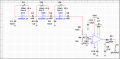
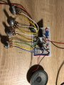
I just finished soldering a special noise machine for a friend of mine to use for his live performances. I wanted to get some advice on what kind of material I should use for housing my circuit board and what I should be aware when I'm making this decision. I just want to make sure that whatever I decide to use doesn't short out my project.

As far as the size, the board I used was an Adafruit (5 x 3 x 0.5 inches). I will have to drill some holes for four potentiometers, an LED and a 9V (DC) jack.

Any advice would be fantastic.

Thanks,
Sam
 

Attachments

AnalogKid

Joined Aug 1, 2013
10,971
Digi-Key, Mouser, and many surplus companies have enclosures, some with removable panels. That is a nice feature because it makes the interface area easier to work on, and if you make a mistake you don't have to replace the entire box. Local HVAC companies are a good source of scrap sheet metal for replacement panels. Of course, ebay has very low cost enclosures if you can sort through thousands of hits.

Something about your layout doesn't make sense to me. Can you post your schematic?

ak
 

Externet

Joined Nov 29, 2005
2,198
I use aluminium housings from disemboweled (small) power inverters, old modems, picked at pawn shops and junkers. They are nearly bulletproof. As they are extrusions, can be sawed-off, shortening to fit needs.
 

Thread Starter

drmanmachine

Joined Mar 12, 2016
68
Digi-Key, Mouser, and many surplus companies have enclosures, some with removable panels. That is a nice feature because it makes the interface area easier to work on, and if you make a mistake you don't have to replace the entire box. Local HVAC companies are a good source of scrap sheet metal for replacement panels. Of course, ebay has very low cost enclosures if you can sort through thousands of hits.

Something about your layout doesn't make sense to me. Can you post your schematic?

ak
The layout is not completely finished yet. There are a couple of more components that will be added (a switch, dc jack). The Schmitt Triggers are getting a 9V input. (Doesn't show it on the schematic).
 

Attachments

AnalogKid

Joined Aug 1, 2013
10,971
You have too many pins grounded in the image of post #1. For unused CMOS gates, only the *inputs* should be tied to GND or Vdd. The outputs must be left open circuit.

ak
 

DickCappels

Joined Aug 21, 2008
10,140
Looking at the values of the resistor and capacitors it does not "feel" like it would be very sensitive to external electric fields so a plastic box can be used.

If it turns out that you get some interference, you can always put some copper tape, or a piece of copper clad pcb material in the case to provide shielding.

In the case of using plastic keep in mind that it can melt and some plastics can burn pretty well, so limit the power available to the box so that in the event of a failure you don't wind up with a flaming ball of plastic.
 

Thread Starter

drmanmachine

Joined Mar 12, 2016
68
You have too many pins grounded in the image of post #1. For unused CMOS gates, only the *inputs* should be tied to GND or Vdd. The outputs must be left open circuit.

ak
I had no idea. Just so I understand why, how come they must be left open? What happens if I leave them grounded?
 

AnalogKid

Joined Aug 1, 2013
10,971
Each section is an inverter. With the input grounded, the output goes high. If the output is grounded, that high tries to short out the system power supply through a chip rated for only 4 mA. Failure is not immediate because a CMOS output has some current limiting built in, but the part will fail eventually.

If you tie the unused inputs high, then the outputs go low. In this case, grounding them is not guaranteed death, but it is a horribly bad practice. They don't generate or radiate any noise, and should be left unconnected. An unconnected output is like a wall socket with nothing plugged into it - it just sits there.

A third option is to tie unused inputs to other outputs. They do not load the output or affect the circuit, and often it is a more convenient pc board routing than snaking a trace to Vdd or Vss. With three unused inverters in a row, it is tempting to connect them in series because then you only have to ground the input to the first one. This is not a good idea, because later you might want to use one of them, and now you have to deal with the consequences of breaking the chain. Better to deal with each input independently; then with only one trace cut the gate is freed up for use and the remaining gates are undisturbed. One cut and no jumpers is better than two cuts and one jumper.

To keep track of things like this, always put all sections of multi-gate packages on the schematic even if some of them are unused. This keeps them in your thinking so you don't forget to deal with them.

ak
 
Last edited:

Thread Starter

drmanmachine

Joined Mar 12, 2016
68
Each section is an inverter. With the input grounded, the output goes high. If the output is grounded, that high tries to short out the system power supply through a chip rated for only 4 mA. Failure is not immediate because a CMOS output has some current limiting built in, but the part will fail eventually.

If you tie the unused inputs high, then the outputs go low. In this case, grounding them is not guaranteed death, but it is a horribly bad practice. They don't generate or radiate any noise, and should be left unconnected. An unconnected output is like a wall socket with nothing plugged into it - it just sits there.

ak
Makes perfect sense. I'll be sure to remove them. Does it make a difference if the inputs are left unconnected?
 

AnalogKid

Joined Aug 1, 2013
10,971
Does it make a difference if the inputs are left unconnected?
A large difference. Two things.

First, a CMOS input is an extremely high impedance, like gigaohms. This makes it an antenna picking up everything around it, and trying to process it (AND, OR, Invert, whatever) into an output. This can make the output bang around all over the place, generating both radiated and conducted noise (into the power rails). In fact, a gate input can see its own output and turn into a 100 MHz oscillator just for fun.

Second, remember that a CMOS inverter is in fact just a very high gain inverting *linear* amplifier. If the floating input wanders around the transition level, the output can try to make Vdd/2 volts. This means both the high and low output transistors are on at the same time, something the chip is not designed for, again drawing way too much current. smoke flames death.

NOTE - The CD40106 has Schmitt input stages before the linear amplifier stuff described above, and this prevents linear region operation and most of the spontaneous oscillation. It does not prevent noise pickup and generation, so terminating all unused inputs still is an unbending rule.

ak
 

Thread Starter

drmanmachine

Joined Mar 12, 2016
68
A large difference. Two things.

First, a CMOS input is an extremely high impedance, like gigaohms. This makes it an antenna picking up everything around it, and trying to process it (AND, OR, Invert, whatever) into an output. This can make the output bang around all over the place, generating both radiated and conducted noise (into the power rails). In fact, a gate input can see its own output and turn into a 100 MHz oscillator just for fun.

Second, remember that a CMOS inverter is in fact just a very high gain inverting *linear* amplifier. If the floating input wanders around the transition level, the output can try to make Vdd/2 volts. This means both the high and low output transistors are on at the same time, something the chip is not designed for, again drawing way too much current. smoke flames death.

NOTE - The CD40106 has Schmitt input stages before the linear amplifier stuff described above, and this prevents linear region operation and most of the spontaneous oscillation. It does not prevent noise pickup and generation, so terminating all unused inputs still is an unbending rule.

ak
Thanks man. I removed all the output pin connections and left them unconnected. This is very informative moving forward if I decide to use the 40106 for future oscillator projects.

A sort of unrelated question, if I wanted to design a variable sawtooth audio oscillator using the 40106, is that doable?
 

Attachments

Top