Home school circuit analysis class suggestions needed

Thread Starter

rpschultz

Joined Nov 23, 2022
416
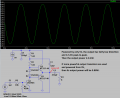
Maybe this using the LM386? The data sheet has a couple examples of how to power a 4-32Ω speaker.
1679494456268.png

The 1.2k resistor across pins 1 and 8 control the gain. Open is default gain of 20, shorted is gain of 200. So a pot (10k?) would serve as a volume control?
 

Attachments

AnalogKid

Joined Aug 1, 2013
11,056
A pot would serve as a gain control with a minimum gain of 20, as opposed to a volume control that can take the signal all the way down to zero.

There are many low-cost modules on ebay using the LM386 as a microphone preamp. While it can perform that function, the 386 is built from the ground (!) up to be a speaker driver. As such, it has relatively high noise and distortion in a low-signal-level application.

But it is just about bulletproof as a beginner's speaker driver. Adding a 1-transistor or 741 preamp to its input is a common approach to an el-cheapo intercom, headphone (earbud) driver, and other non-hifi applications.

ak
 

MisterBill2

Joined Jan 23, 2018
18,600
One project that I think is doable is a clap activated light.
Clap once and an LED turns on.
Clap again and the LED turns off.
It incorporates analog circuits, amplifiers, filters, and flip-flops.
The clapper light control could be a good place to start with a two-transistor flipflop, which will be a bit of a circuit analysis challenge as well as simple to build. And lots of samples from back in the sixties. Then add the clap sensing trigger. No need to use complex IC devices for the FF.
 

MrChips

Joined Oct 2, 2009
30,824
LM386 and LM741 are very different.

LM741 is a classic, out of date, operational amplifier. It is not suitable for your project. It is not recommended for new designs.

LM386 is a low power amplifier intended to drive a loudspeaker. You can try it as a mic to speaker amplifier.

I would still suggest that you try the clap activated light project.
 

AnalogKid

Joined Aug 1, 2013
11,056
Except for LS1, that is the 1-transistor *preamp* I mentioned. The circuit is a very simple inverting amplifier

R2 is bias current for the electret mic cartridge.
R2 is the negative feedback resistor. In terms of an inverting opamp circuit, the output impedance of the mic is the input resistor.
R3 is the output pull-up device.
Q1 is the output pull-down device.

R1 also stabilizes the DC operating point of the transistor. C1 prevents the mic cartridge inherent DC output voltage from messing up this.

Your attached schematic will work as a low-power speaker driver, but it is very inefficient. Also, there is constant DC through the speaker in addition to the audio, and this DC will cause significant transistor heating. Still, it is a classic teaching circuit because of its simplicity and its issues.

ak
 

Thread Starter

rpschultz

Joined Nov 23, 2022
416
On Monday, we are doing Voltage Dividers. So today I'm preparing for the week after that, basic transistor function. I've been looking at the following circuit in Eagle:
2N2394VoltageDivider.png

Using R3 like a POT, when R3 is 0 or below about 6k the base voltage is above 0.7v and the transistor is on. As I increase R3 further above 6k, the base voltage reduces down to below .7v and the cuts off. But when I breadboard this the LED is always on. I can't make it turn off, even using larger pot values.

What am I missing?
 

AnalogKid

Joined Aug 1, 2013
11,056
Check your wiring.

Also - If R3 is decreased to 90 ohms or less, the base current will be above 50 mA. This is a typical Absolute Maximum value on small signal transistor data sheets. If the pot is turned all the say down for just milliseconds, the transistor probably is blown.

One way to protect against this is to add a 3rd resistor. This can be between the transistor base and the R1 - R3 node, or between the top of R3 and V1 . In a 5 V circuit, something in the 100 - 200 ohm range should prevent disaster. That value is independent of the max value of R3.

ak
 

Thread Starter

rpschultz

Joined Nov 23, 2022
416
Ah, that's probably it. Good catch. Using a 150Ω resistor would give me a max current of 27 mA with pot at zero.
I searched the datasheet and couldn't find where it says max base current is 50 mA.

Also, I have this transistor kit, are there other NPN's that would be better suited for this application? Besides NPN vs PNP, I really don't know the difference between any of them.

1679764057099.png
 

MaxHeadRoom

Joined Jul 18, 2013
28,702
I would think going with the modern device in the Mosfet range, there is one of the old originals, 2n7000, that is still popular and very useful for teaching small projects illustrating the characteristics of Mosfet.
It has a logic level - voltage controlled gate, as opposed to the bi-polar transistor current controlled base.
 

Attachments

Last edited:

WBahn

Joined Mar 31, 2012
30,082
At 10 kΩ, with no connection to the base, the voltage would be about 450 mV. That's high enough to get SOME base current flowing. A pretty decent rule of thumb is that the Vbe of a silicon BJT, at room temperature, changes by about 60 mV per factor of ten change in base current. So if you have a transistor that happens to have a high current gain, that will lower the base current, and hence the Vbe. If you are then just letting a few milliamps of collector current through, that will again drop the Vbe needed to do it. Then there's the question of what your supply voltage actually is. If it's actually a bit higher than 5 V, that will increase the Vbe.

Put another 1 kΩ resistor in parallel with the one you already have and you should be able to turn the LED off.

Better yet, put another resistor in series with the 10 kΩ pot to limit how low the base resistance can get. Pick it so that when the pot is turned all the way to zero that no more than about 20 mA of base current can flow. That number comes from taking the max allowed collector current of 200 mA and then using a beta of 10 in saturation. Something like a 220 Ω resistor should work. You can either put it in series with the pot, or in series with the base junction.
 

Thread Starter

rpschultz

Joined Nov 23, 2022
416
Like this:
2N2394VoltageDivider.png

So the ratio of R3/R1 practically needs to be 20:1 or so with a 5V supply to get the LED to turn off by reducing Vbe to <400-500 mA. So a 20k pot and 1k, etc. The model I'm using for the 2N3904 in Eagle isn't that sensitive and it turns on/off easier.
 

Thread Starter

rpschultz

Joined Nov 23, 2022
416
I would think going with the modern device in the Mosfet range, there is one of the old originals, 2n7000, that is still popular and very useful for teaching small projects illustrating the characteristics of Mosfet.
It has a logic level - voltage controlled gate, as opposed to the bi-polar transistor current controlled base.
FET's have their advantages, but I decided to stay away from them since these students would probably fry a bunch of them due to their static sensitivity. Simple BJT's should be fine for teaching the basics.
 

MaxHeadRoom

Joined Jul 18, 2013
28,702
FET's have their advantages, but I decided to stay away from them since these students would probably fry a bunch of them due to their static sensitivity. Simple BJT's should be fine for teaching the basics.
Just that working with them since the 80's -90's , I have never really observed any particular care with the question of static damage etc, and do not recall ever having any failures of all the ones I have implemented. ;)
 

Thread Starter

rpschultz

Joined Nov 23, 2022
416
Just that working with them since the 80's -90's , I have never really observed any particular care with the question of static damage etc, and do not recall ever having any failures of all the ones I have implemented. ;)
You may be right, I'm a novice. But based on what others have said, FET's can be problematic when working with students. That, and my transistor kit was all BJT's:)
 

MaxHeadRoom

Joined Jul 18, 2013
28,702
Having started my electronics career in the Valve/Tube era, I took to the FET easily , as these are voltage controlled devices also
AKA Transconductance amplifiers, as opposed to the transistor which is current operated.
 

Audioguru again

Joined Oct 21, 2019
6,710
You found an "amplifier" circuit from Circuit Digest students in India with many problems.
It produces almost no output power and produces almost no voltage gain.

Its 10k output resistor is a voltage divider with the 8 ohm speaker cutting the normal 6V peak-to-peak output down to a severely distorted output of only 0.02V peak-to-peak.
 

Attachments

Last edited:

Thread Starter

rpschultz

Joined Nov 23, 2022
416
You found an "amplifier" circuit from Circuit Digest students in India with many problems.
It produces almost no output problems and produces almost no voltage gain.

Its 10k output resistor is a voltage divider with the 8 ohm speaker cutting the normal 6V peak-to-peak output down to a severely distorted output of only 0.02V peak-to-peak.
Yes you're right, I couldn't get it to work. How could I improve it?
 

Audioguru again

Joined Oct 21, 2019
6,710
I have this transistor kit, are there other NPN's that would be better suited for this application? Besides NPN vs PNP, I really don't know the difference between any of them.
All transistors have a detailed datasheet. The maximum collector current of a 2N3904 is 200mA, its maximum base current is 20mA and its maximum heating is 625mW.

Please do not copy defective circuits from students on the other side of the world.
 
Top