 Facebook
 Google
 GitHub
 Linkedin
Whole day sitting on the task I got in stupor. Probably You may give a hint in what direction to dig further....
The problem is of need for 100 pieces identical 50 mA CC (constant current) stabilizers, having common ground and + in the regulator side. Working voltage 580V(!)
First my idea was Wilson current mirror, and my Spice model works with that brilliantly, BUT.... if Farnell has no ANY 600V candidate for p-channel mosfet that’s bad sign, and Octopart has only few for ... 18 USD piece, absolute nonsense. While n-channel is plethora for 24 cents a piece. So, seems working with n-channel is mandatory.
Then I turned the circ in all possible ways but only result is common plus and separate grounds what is absolute not permitted. Logically, moving the load from drain to source kills the stabilizing functionality. Adding any emitter follower kills the stabilizing effect by great part too.
So I guess the regulator with current sense element in series with load would be best choice, so forget the Wilson. But even then I cannot to see any other choice as to put load in the source instead of drain - as soon it is drain the common minus is lost what was so much needed (it is actually galvanic bath very body).
So, what may be SIMPLE design ideas for such 600V 50 mA current source?
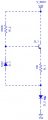
Probably try the sense resistor upper than load in the source, serially, and TL431 between gate and sense resistor`s bottom regulates all?? I wonder the www is full of similar circuits on npn bjt, but nowhere I was able to find anyone had used such made on mosfet. Why?
The problem is of need for 100 pieces identical 50 mA CC (constant current) stabilizers, having common ground and + in the regulator side. Working voltage 580V(!)
First my idea was Wilson current mirror, and my Spice model works with that brilliantly, BUT.... if Farnell has no ANY 600V candidate for p-channel mosfet that’s bad sign, and Octopart has only few for ... 18 USD piece, absolute nonsense. While n-channel is plethora for 24 cents a piece. So, seems working with n-channel is mandatory.
Then I turned the circ in all possible ways but only result is common plus and separate grounds what is absolute not permitted. Logically, moving the load from drain to source kills the stabilizing functionality. Adding any emitter follower kills the stabilizing effect by great part too.
So I guess the regulator with current sense element in series with load would be best choice, so forget the Wilson. But even then I cannot to see any other choice as to put load in the source instead of drain - as soon it is drain the common minus is lost what was so much needed (it is actually galvanic bath very body).
So, what may be SIMPLE design ideas for such 600V 50 mA current source?
Probably try the sense resistor upper than load in the source, serially, and TL431 between gate and sense resistor`s bottom regulates all?? I wonder the www is full of similar circuits on npn bjt, but nowhere I was able to find anyone had used such made on mosfet. Why?
Last edited:


")


