High side switch

Thread Starter

barg

Joined Dec 23, 2015
129
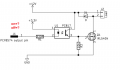
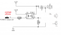
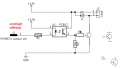
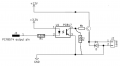
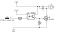
Hello, i would like to switch the 12v side instead of the ground side as in the attched. Meaning- connecting the ground constant and switching on/off with the 12v. can you advice how it can be done? (keeping the opto and nch fet)
 

Attachments

Irving

Joined Jan 30, 2016
4,995
Short answer - it can't with an N-Channel MOSFET. The gate voltage has to be > source voltage, ie ~20v for a 12v supply.
 

Irving

Joined Jan 30, 2016
4,995
Alternatively, use the existing setup to control a relay to switch the 12v. Viability depends on how much current needs to be switched.
 

Thread Starter

barg

Joined Dec 23, 2015
129
Thank you! got the idea. if using P-channel instead, except that n-ch is more common and heat dissapation for higher currents, is there any dissadvantages for using P-ch instead? current suppose to be at max 40mamps
 

Thread Starter

barg

Joined Dec 23, 2015
129
in addition, if choosing a p-ch fet with vGs 20v, is It enough if i need to change it to work with 24v instead of 12v? as the Gate is connected in the schematic also to the same positive rail
 
Last edited:

Irving

Joined Jan 30, 2016
4,995
Thank you! got the idea. if using P-channel instead, except that n-ch is more common and heat dissapation for higher currents, is there any dissadvantages for using P-ch instead? current suppose to be at max 40mamps
If only 40mA then almost any p-channel will do as long as Vgs > -10 to ensure its hard on.
eg Infineon IRFU5305PBF Vds(max) 55v, Rds(on)=65mOhm Vgs(max)=20v good for 5A or so without a heatsink.

in addition, if choosing a p-ch fet with vGs 30v, is It enough if i need to change it to work with 24v instead of 12v?
Best to pick a p-ch FET that is good for your desired Rds(on). If its Vgs spec <24v simply add a 12v zener from G to S to clamp Vgs to 12v

1767812520941.png
 
Last edited:

MrChips

Joined Oct 2, 2009
34,626
In order to turn on the MOSFET, you need to increase VGS to be equal or greater than the VGS threshold voltage.
For a high-side switch, you need a P-channel MOSFET as shown in the previous drawings.
 

MisterBill2

Joined Jan 23, 2018
27,159
Irving did it in post #8. You could do it with the same n-channel mosfet is in the low side circuit BUT you would need an isolated gate bias voltage source to make it work.
 

Thread Starter

barg

Joined Dec 23, 2015
129
If only 40mA then almost any p-channel will do as long as Vgs > -10 to ensure its hard on.
eg Infineon IRFU5305PBF Vds(max) 55v, Rds(on)=65mOhm Vgs(max)=20v good for 5A or so without a heatsink.


Best to pick a p-ch FET that is good for your desired Rds(on). If its Vgs spec <24v simply add a 12v zener from G to S to clamp Vgs to 12v

View attachment 361739
Hi, can you advice what should be the led voltage from the mcu (high / low) to get this nfet on and off as in the attached? as its oposite from nch-fet? or its the same- for on=high/off=low?
 

Attachments

Sensacell

Joined Jun 19, 2012
3,767
Thank you! got the idea. if using P-channel instead, except that n-ch is more common and heat dissapation for higher currents, is there any dissadvantages for using P-ch instead? current suppose to be at max 40mamps


An alternative idea is to use a Photovoltaic isolator to drive an N-CH FET - the opto generates a floating voltage that can drive the gate directly.
The main drawbacks are: (a) it's kinda slow... (b) it takes a bit more current on the LED drive side.

https://www.digikey.com/en/products/detail/panasonic-electric-works/APV1121SX/2804730

Then you can use some of those really low RDS-on FETS that can handle crazy amps.
 

Irving

Joined Jan 30, 2016
4,995
An alternative idea is to use a Photovoltaic isolator to drive an N-CH FET - the opto generates a floating voltage that can drive the gate directly.
The main drawbacks are: (a) it's kinda slow... (b) it takes a bit more current on the LED drive side.

https://www.digikey.com/en/products/detail/panasonic-electric-works/APV1121SX/2804730

Then you can use some of those really low RDS-on FETS that can handle crazy amps.
Yes, but he doesn't need crazy amps! And they are a lot more expensive (FD217 about 3 or 4x PC817) and the gate drive is a few uA rather than tens of mA so much more dissipation in MOSFET (for PWM) unless you use a super-low RDS(on) device which is more expensive too. Overkill IMHO, and old-tech.
 

Sensacell

Joined Jun 19, 2012
3,767
Yes, but he doesn't need crazy amps! And they are a lot more expensive (FD217 about 3 or 4x PC817) and the gate drive is a few uA rather than tens of mA so much more dissipation in MOSFET (for PWM) unless you use a super-low RDS(on) device which is more expensive too. Overkill IMHO, and old-tech.
Yes! expensive haha.
Sometimes that slow and expensive floating gate drive really comes in handy though...
 

MisterBill2

Joined Jan 23, 2018
27,159
NPN power transistor, .Collector to location #1, emitter to location #3 base to position #2, but with a resistor in series.
The position numbers from the sketch in post #11. The series resistor for the base value is to limit the base current to that required for saturation based on the transistor data sheet.
 

Thread Starter

barg

Joined Dec 23, 2015
129
NPN power transistor, .Collector to location #1, emitter to location #3 base to position #2, but with a resistor in series.
The position numbers from the sketch in post #11. The series resistor for the base value is to limit the base current to that required for saturation based on the transistor data sheet.
can you look if the attached correct? it seems its switching the gnd?
 

Attachments

Thread Starter

barg

Joined Dec 23, 2015
129
NPN power transistor, .Collector to location #1, emitter to location #3 base to position #2, but with a resistor in series.
The position numbers from the sketch in post #11. The series resistor for the base value is to limit the base current to that required for saturation based on the transistor data sheet.
did you meant this one? as there are two...
 

Attachments

Top