High-side switch with optocoupler

Thread Starter

ElectronicNewbie0

Joined Oct 18, 2025
54
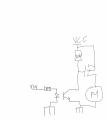
Hello i have been doing some researching and i read that in some cases when u drive a load like a motor or so with a BJT its better to use an optocoupler, making a high -side switch configuration, i have been working on it and i think i could do the circuit.

I found a common used optocoupler, which is PC817
I have been reading the datasheet and i saw that usually its used with a if of 20mA, but It can reach till 50mA, from what i have understood It looks like that higher the current then higher the CTR ratio will be, but with a 20mA i would have already a good CTR ratio, and as output on the transistor i dont really a high capability of driving, since im using a MOSFET.

With that said, what i have done Is basically a high-side switch with optocoupler transistor npn driving the P fet ( i understood now that even a little current can drive a fet in few uS) i calculated the resistor in order to have 20mA driving the led, so what i did Is: 5-1.4/20mA= 180 Ohm

Is this thing correct, there is something missing that i should consider in optocouplers? U as HW Designers what u would consider more? Also is this circuit to excessive and unnecessary or what do u think?

Thanks all.
 

Attachments

panic mode

Joined Oct 10, 2011
4,932
main reason to use optocoupler is to isolate circuits so each side is powered separately using own source.
in such case two GNDs are not tied together, each is local to their own part of the circuit.
1760989119151.png
 

Thread Starter

ElectronicNewbie0

Joined Oct 18, 2025
54
main reason to use optocoupler is to isolate circuits so each side is powered separately using own source.
in such case two GNDs are not tied together, each is local to their own part of the circuit.
View attachment 357395
I didnt get why u added another 10k, i just need a pull-up then It ties gate to gnd and P fet "activates", why adding a second resistor? Like this i will get a voltage divider, but i will have a positive voltage like vcc/2 on p gate secondly i didnt get why u added a diode in parallel to 10k resistor
 

Thread Starter

ElectronicNewbie0

Joined Oct 18, 2025
54
main reason to use optocoupler is to isolate circuits so each side is powered separately using own source.
in such case two GNDs are not tied together, each is local to their own part of the circuit.
View attachment 357395
maybe i understood, that diode may be used as protection? if gate reaches a high voltage caused by motor inductance or miller effect then the diode will start conducting, and all energy into vcc rail, protecting the transistor, right?
 

panic mode

Joined Oct 10, 2011
4,932
I didnt get why u added another 10k, i just need a pull-up then It ties gate to gnd and P fet "activates", why adding a second resistor? Like this i will get a voltage divider, but i will have a positive voltage like vcc/2 on p gate secondly i didn't get why u added a diode in parallel to 10k resistor
the resistors do not need to be those values. i don't know what mosfet you use. while many mosfets will tolerate up to +/-20V for Vgs, plenty of them will not. Some will blow up if Vgs exceeds 10V.

so you need to keep that in mind and make sure that transistor is protected. for Vgs you may want to use divider and suitable zener diode.

any time you are switching inductive load in a DC circuit, you will also want to add suppression across output. usually that is a diode.
 
Last edited:

Thread Starter

ElectronicNewbie0

Joined Oct 18, 2025
54
the resistors do not need to be those values. i don't know what mosfet you use. while many mosfets will tolerate up to +/-20V for Vgs, plenty of them will not. Some will blow up if Vgs exceeds 10V.

so you need to keep that in mind and make sure that transistor is protected. for Vgs you may want to use divider and suitable zener diode.

any time you are switching inductive load in a DC circuit, you will also want to add suppression across output. usually that is a diode.
Oh alright, i understood for the resistor voltage divider part now.

The diode i meant the one in parallel to the 10k, this will make a protection for the transistor itself? So current will flow from gate to directly vcc instead of flowing from gate to the collector and maybe could break the optocoupler?
 

panic mode

Joined Oct 10, 2011
4,932
Oh alright, i understood for the resistor voltage divider part now.

The diode i meant the one in parallel to the 10k, this will make a protection for the transistor itself? So current will flow from gate to directly vcc instead of flowing from gate to the collector and maybe could break the optocoupler?
diode connected to gate is a zener. it is meant to clamp down gate voltage to something that mosfet can handle. with this, high side switch does not need to be limited to 12V, it can work with 24V or 48V or anything in-between (if sized correctly). using only voltage divider, without zener, can also work but only for narrow range of supply voltage
 

Thread Starter

ElectronicNewbie0

Joined Oct 18, 2025
54
diode connected to gate is a zener. it is meant to clamp down gate voltage to something that mosfet can handle. with this, high side switch does not need to be limited to 12V, it can work with 24V or 48V or anything in-between (if sized correctly). using only voltage divider, without zener, can also work but only for narrow range of supply voltage
Ohh alright, thanks i understood, i thought u put a common diode there, but if its a zener i get It now
 

mehmetbey

Joined Apr 10, 2025
11
Hello.
Fix the PC817 led current at 13-18mA with LM317L. Because the CTR value is at the maximum level, between 13-18mA.
Drive the transistor with the PC817 output as well. Maybe it won't be simple, but it will be solid.

Below is the principle diagram. Do not forget to add protection components.


panic mode

Joined Oct 10, 2011
4,932
Its better having low current? What about CTR ratio
even if CTR is low, say 40%. what do you think the input current needs to be if output side is powered by 12V and there is a 10k resistor?
if the output is limited by some 10k value, output current of the optocoupler is limited to 1.2mA.
so input current will need to be bigger so 1.2mA/0.40 = 3mA.

Note.... this is MUCH less than 20mA. and 20mA is usually stated as absolute max limit for many products (logic ICs, MSU GPIOs etc.). and when something has a limit of 20mA, you probably want to stay well within, such as within 10-15mA,
so yes - in general, lower current is better.
 
Top