Facebook
 Google
 GitHub
 Linkedin
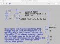
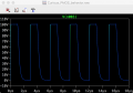
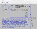
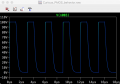
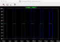
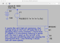
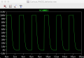
Hi - I have been trying to teach myself a little bit about electronics, and today that was high-side switching with a power P-MOSFET (IRF9640, picked essentially at random from LTspice's library). I have seen the small-signal model for mosfets and I think that I sort of understand what is going on with small signals, but with this circuit I saw a curious exponential drop on the turn-off part of the waveform that I didn't understand.
Any hints (or links to websites or books) that you might have would be appreciated.
(pictures of the circuit and the drain voltage waveform are attached)
Any hints (or links to websites or books) that you might have would be appreciated.
(pictures of the circuit and the drain voltage waveform are attached)
Attachments
-
 505.1 KB Views: 18
 -
 142.2 KB Views: 15