The LED hooked up to pins 8/12/5 (the right hand one on the schematic) has full power (700mA) but no strobe, while the other LED has strobe but is only pulling 10mA...and I switched the LEDs to see if that made a difference...but it's the same.
It takes a while to get good at it.
A clean, tinned iron at the right temp, clean parts, clean solder, and a bit of flux makes things go pretty well.
I'm using a IRF640...don't know if that's an equivalent MOSFET Wookie. I asked the guy in the electronics shop, he looked at what you sent and handed me these things. I think I have them plugged in right...downloaded a data sheet.
There are differences.
The IRF640 is for moderately high voltages (Vdss=200)
The IRLR7807 is rated for Vdss=30.
Besides that, the IRF640 is twice the size, rated for less than half the current, requires twice the gate voltage to turn on, and requires 10x the gate charge which means 20x the current to charge/discharge the gate.
So no, it's not equivalent. It is, however, a MOSFET - just one with very different specifications.
One LED is very dim but flashes...the other is very bright and does not appear to flash. In actuality, I think it may be strobing, but at a much higher rate...
Short C1 to ground. One LED should be on, the other off.
Then short C1 to +V (the battery positive) - the one that was on should turn off, and the one off should turn on.
You may have shorted R3 or Q1 to ground.
If the LEDs are on the same heat sink, or if their grounds are connected together, it won't work properly.
The LED hooked up to pins 8/12/5 (the right hand one on the schematic) has full power (700mA) but no strobe, while the other LED has strobe but is only pulling 10mA...and I switched the LEDs to see if that made a difference...but it's the same.
It's doing this: D2 is on constant with 700mA current, D1 is strobing but only has 10mA current.
When I short C1 to ground, D2 is on constant and D1 turns off.
When I short C1 to V+, D1 turns on at full power but is no longer strobing. Then if I let go of the short it goes back to as it was, but if I short it a few times, then D2 turns off completely when I let go of the short and D1 stays on full power with no strobe...
Maybe My MOSFTES aren't working right. When I switch them around I get a different response...now D2 stays on while D1 strobes at full power. Bad MOSFETS?
If you get a chance, look for logic level MOSFETs, which is what I was talking about last page. Your power supply is almost enough to drive them, which could be contributing to the problem.
I'm looking forward to getting the parts from Wookie, never tried to use surface mount off of a 0.1" spaced perfboard before, this will be interesting (hopefully not in a Chinese sort of way).
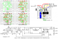
OK, I redrew Wookies schematic a bit. Since the 7556 current is somewhat self limiting (I don't think it can burn out in this schematic) I dropped the resistors R3 and R4 down. If this schematic gets any longer it will be rearranged.
I now have MOSFETs, I've added them to my PaintCAD's templates, so now the build will continue.
I suppose you could use 100 Ohm resistors on the gates, and it'll work just fine - until you experience a fault like the gate shorting to the drain or source. Then the 7556 will get mighty toasty as it tries to source or sink that much current. You'll probably wind up having to replace both the 7556 and the failed MOSFET.
The idea of using a higher value gate resistor is to make the circuit more fault-tolerant.
My limited experience with the 7556 is that they are not like the 556 (or 555), they give what they can, and no more. If the chip sources 50ma the 100Ω will drop 5V, the rest will be in the chip, less than a ¼W. What is usually a PITA is an asset here.
Of course, if the gate shorts the puck puck will have its way with the 7556. I'm planing on using a machine pin socket with the IC.
My concern is switching speed. I'm not experienced with MOSFETs, but this is already switching between two high current LEDs connected to what is basically a switching power supply. I want to keep that transistion as short as possible.
I'm thinking of leaving short wires off the board that can be easily spliced onto, just twist them together and tape em up.
I finally got my computer fixed in the wee hours of the morning, but we have company this afternoon/evening - our Swiss cousins - they brought Swiss chocolate
I'll throw the circuits into a simulation later, just to see what the switching times might be.
But like I said before, the switching times really aren't an issue here. It'll be fine if both MOSFETs are on simultaneously; they will be no matter how fast or slow the switching times are. That's because they turn on faster than they turn off. The nice thing about that, is the power dissipation in the MOSFETs should be minimal.
Now that I think about it more - those 7556 timers will sink about 10x as much current as they will source. That could lead to both MOSFETs being off at the same time. While the BuckPuck is protected from this situation, it will mean that the MOSFETs will switch while maximum voltage is across them, which would lead to more power dissipation.
I'm going to have to simulate this to prove or disprove this theory.
I've got to go visit my future nephew in law at the hospital, I mentioned elsewhere, but he slipped on Chistmas Eve on his way to my house (his yard) and broke his leg below the knee several places.
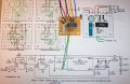
OK, the 1st one is complete, I need to mount the LED and try it out. A good use for the green wires, I can add a 10µF or 100µF cap to slow things down. A nice side bonus for test out.
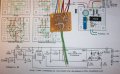
I've got some drilling to do on the LED heat sink. I only have one LED to test with, so I'll use 4 or 5 1N4007 diodes in series to simulate a second LED. I might stick a conventional red LED with a resistor across them to see it flash.
Do you have an adjustable BuckPuck?
If so, you might want to check it's current output the way it explains it in the datasheet.
Once you get it running, see if you get a blip of higher voltage at the output of the BuckPuck when the MOSFETs switch. If so, they're not overlapping their ON states, and the 100 Ohm resistors will need to be increased.
 Facebook
 Google
 GitHub
 Linkedin