High Amperage with a Potentiometer - Circuit Design Needed

Thread Starter

Michael Dougan

Joined Dec 4, 2016
10
Hello!
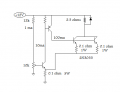
I am trying to run a somewhat beefy motor using a power adapter that outputs 12 volts, 8 amps DC. I'd like to be able to vary the speed of the motor using a potentiometer, preferably around 10k ohm or 100k ohm. I need a circuit design to power my motor with the potentiometer.

I also want the circuit to use no microcontrollers, digital potentiometers, or PWM of any sort. I'd like it to contain more basic circuit components, like transistors, resistors, and possibly capacitors. And the only power source should be the aforementioned power adapter, and no separate power sources like batteries to provide signals to the transistor(s).

If someone could specify a circuit design, I would appreciate it greatly!
 

wayneh

Joined Sep 9, 2010
18,089
If you're avoiding PWM because it's too "complex", don't. You can buy PWM motor controllers on e-bay for next to nothing. No need to build one yourself.
 

Thread Starter

Michael Dougan

Joined Dec 4, 2016
10
The motor is a 20v DC.

I already know how to power it using PWM (I'd have to figure out the right kind of transistor, and then wire it up to my Arduino no sweat), but for this particular project I want to use basic components, since it seems that all I ever use for my electromechanical projects is my Arduino, one transistor, and Google. I want to learn more about other ways of varying a high voltage.

(Another note: I don't want to use a rheostat, they're a bit too expensive and hard to find)
 

wayneh

Joined Sep 9, 2010
18,089

Thread Starter

Michael Dougan

Joined Dec 4, 2016
10

Deleted member 115935

Joined Dec 31, 1969
0
For reference,

this motor controller has no speed feedback,
and is a good definition of an amplifier,
high impedance in ,low impedance out..

As such , you can use all the amplifier options,
Class A / B / C / D

PWM, PDM , etc etc

If you use a simple transistor pot system, thats a class A amplifier,
your dissipating the heat either in the amplifier heat sink or the motor,
the power dissipation is fairly constant.

Looking at it as an amplifier,
Class B would be better for power efficiency than A
but best power efficiency would be Class D,

Class D is a Pulse type, where the output driver is either on or off,
and as its low bandwidth, a much easier circuit than an audio amp.

Make an audio amp if you want to learn analog,
 

jpanhalt

Joined Jan 18, 2008
11,087
Look at transistorized light dimmer circuits for cars and airplanes from the 1970's or so. They just used a power transistor and a pot on the base that controlled the current.

If it is a 20VDC motor, how well does it run on your 12V, 8A supply?

John
 

DickCappels

Joined Aug 21, 2008
10,661
You didn't ask whether it was a good idea, you just asked how to do it, so here is one answer:

The Edfet Buffer in the image below takes a fairly high resistance input and can supply many amps of output current. The initial use was in a vertical reflection circuit in an avionics monitor.

upload_2016-12-5_17-38-4.png

In order for the output to get all the way to 12 volts for your application R1 should go to about +20 volts to provide enough gate drive.

To drive a motor the input connects to the wiper of a potentiometer with one end of the pot connected to +12 and the other end connected to ground. 5K is a good value for the pot. 10K should work fine too. The BUZ73 is good for up to 7 amps but I suggest using one rated for a much higher current because the current will be high before the motor begins to rotate.

To minimize damage from reverse currents, you can add two 1N400X (1N4001 through 1N4007) to the output. The cathode of one connects to +12V and the anode of the other connects to ground.

It might be nice to add current limiting but given how little we know about the load it might be best left until later.
 

dannyf

Joined Sep 13, 2015
2,197
I'd like it to contain more basic circuit components, like transistors, resistors, and possibly capacitors.
fairly easy: a basic potentialmeter buffered by an emitter follower, with the motor on its emitter, would do.

At the kind of current / voltage you are looking at, prepare some beefy transistors and ***large*** heatsink, or lots of fans.
 

Thread Starter

Michael Dougan

Joined Dec 4, 2016
10
fairly easy: a basic potentialmeter buffered by an emitter follower, with the motor on its emitter, would do.

At the kind of current / voltage you are looking at, prepare some beefy transistors and ***large*** heatsink, or lots of fans.
I recently found a 2n3055 NPN transistor at Radioshack, do you think it would work for a setup like this?
 

#12

Joined Nov 30, 2010
18,224
I recently found a 2n3055 NPN transistor at Radioshack, do you think it would work for a setup like this?
12V @ 8 amps, adjustable to zero? That's 96 watts. Start with 2 of the big transistors, heat sinks, and a fan.
If you want this reliable for years, try about 4 transistors.

See why we keep barking at pulse width modulation? It takes most of the heat problem away.
 

Thread Starter

Michael Dougan

Joined Dec 4, 2016
10
12V @ 8 amps, adjustable to zero? That's 96 watts. Start with 2 of the big transistors, heat sinks, and a fan.
If you want this reliable for years, try about 4 transistors.

See why we keep barking at pulse width modulation? It takes most of the heat problem away.
I see what you mean. I misread the specifications; it's rated for 115w, but not continuously, as it will heat up above 25 C. Could you perhaps point me in the right direction on how to use 2 (or perhaps 4) transistors at once for a single output? Like, how would I hook up the Base pins?And what would be the best potentiometer+resistor(s) setup for that?
 

#12

Joined Nov 30, 2010
18,224
Here's a preliminary drawing. One big assumption is that a 20V 8A motor has 2.5 ohms, so that would limit it to 4.8 amps at 12V. That could be awfully wrong if the motor is stalled, but I don't know much about DC motors.
ps, that input voltage divider looks wrong, but I'm assuming Q1 is going to load down the voltage. If the pot has the motor going wide open before it gets to the stop, increase the 12k resistor.
 

Attachments

Last edited:

wayneh

Joined Sep 9, 2010
18,089
If you really want old school, you could just switch in a few 12V bulbs in series with the motor. A single headlight would cut the voltage and current roughly in half. Turning on the high beam or another bulb in parallel with the first would take you to maybe 3/4 speed. The bulbs are purpose built to dissipate heat and give visual feedback to boot.
 
Top