Facebook
 Google
 GitHub
 Linkedin
Skip to needed info and questions if you want.
Background:
I started a project, converting DIY ac welder to DC. I dont like to follow along blindly, I like to learn and understand what i'm doing. Poof it eats up madding amount of time. I'm a dad, student and part time worker, so i'm sort on that atm. Currently my attempt at makeing bus bars with out a proper Machine shop came out less than perfect leading me down a new path, needing new information.
I am at my wits ends atm and I need an answer to my question(s) but would also like to be pointed at the books or websites that would help me figure this stuff out on my own in the future.
Needed info:
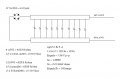
I have 10 Malloory 10,000 50 VDC CGS103U050R4C, That I am putting in parallel to get the ripple current and high energy storage for this welding application. The capacitor bank will be feed by a single phase 60hz 120v ac stepped down, to about 30v ac feed to a 150 amp bridge rectifier.working with 4 awg wire. duty cycle of about 20% @ 90 amps and max out put is about 125amps but the duty cycle drops to like 10%. we are talking 2 min weld time max out of 10 min.
I tried to make 2 banks, with 4 bus bars attaching the bus bars to the top of the capacitors. Had issues keeping bus bars straight, drilling holes prefect, and not a lot of room to keep them from short circuiting.
4 and 6 awg lug connectors will not fit the capacitors, too big and would be hard to keep them from shorting. lead me to the bus bar idea.
questions
Then it hit me:
New idea: Each capacitor only supply's part of the current, therefore I could use smaller wire to feed each screw top capacitor to a thick copper bus bar.
Does this seem like correct circuit thinking? Will this work safely?
How to gauge wire? +20% of ripple current of each capacitors 8.5 amps @ 120hz. ?
Also my understanding is that in welding the capacitor bank ripple current only needs to supply 30-40% of total welding current. I went well above this just to be sure.
Thanks for your time.
Background:
I started a project, converting DIY ac welder to DC. I dont like to follow along blindly, I like to learn and understand what i'm doing. Poof it eats up madding amount of time. I'm a dad, student and part time worker, so i'm sort on that atm. Currently my attempt at makeing bus bars with out a proper Machine shop came out less than perfect leading me down a new path, needing new information.
I am at my wits ends atm and I need an answer to my question(s) but would also like to be pointed at the books or websites that would help me figure this stuff out on my own in the future.
Needed info:
I have 10 Malloory 10,000 50 VDC CGS103U050R4C, That I am putting in parallel to get the ripple current and high energy storage for this welding application. The capacitor bank will be feed by a single phase 60hz 120v ac stepped down, to about 30v ac feed to a 150 amp bridge rectifier.working with 4 awg wire. duty cycle of about 20% @ 90 amps and max out put is about 125amps but the duty cycle drops to like 10%. we are talking 2 min weld time max out of 10 min.
I tried to make 2 banks, with 4 bus bars attaching the bus bars to the top of the capacitors. Had issues keeping bus bars straight, drilling holes prefect, and not a lot of room to keep them from short circuiting.
4 and 6 awg lug connectors will not fit the capacitors, too big and would be hard to keep them from shorting. lead me to the bus bar idea.
questions
Then it hit me:
New idea: Each capacitor only supply's part of the current, therefore I could use smaller wire to feed each screw top capacitor to a thick copper bus bar.
Does this seem like correct circuit thinking? Will this work safely?
How to gauge wire? +20% of ripple current of each capacitors 8.5 amps @ 120hz. ?
Also my understanding is that in welding the capacitor bank ripple current only needs to supply 30-40% of total welding current. I went well above this just to be sure.
Thanks for your time.