Facebook
 Google
 GitHub
 Linkedin
Hello I'm sorry this is my first post but I have wound myself up something chronic.
I am making a novelty clock for my son's birthday in late May 2025 (he will be 25, I am 55, these are the times we live in). I realised it's going to be a little dark inside the clock and had a great idea to have a function that if you touched the handle of the clock (it's like a wide carriage clock design) four LEDs would light up inside for a few seconds.
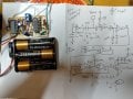
I designed a circuit. It wasn't easy, I've always used two wire touch switches in the past with no problem (presumably using skin resistance), but finding a simple single wire touch switch (presumably using hand capacitance??) was not easy. In the end I found one using Schmitt triggers and breadboarded it up but frustratingly couldn't get the other Schmitt triggers to make a monostable to keep the light on. It was massively unstable all around so I ended up using the other inverters to get it under control and used a 4001 as a plain Monostable. It wasn't pretty but it sort of worked with a single LED so I made it up on a stripboard and got on with the other parts.
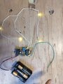
As I was getting further forward with the mechanical parts I thought I would make up the four LEDs using dolls house cable I had to make sure the circuit worked 'in the field'. I had two sets of two white LEDs in parallel on about eight inches of cable. They worked fine triggered off the touch switch.
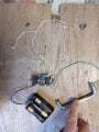
Then I found a handle I liked, and linked it to the circuit with a solder tag and screw. The LEDs came on on power up, but stayed off. If I detached the handle, the circuit worked. If I kept the handle, but replaced the LEDs with four LEDs pushed into my terminal blocked, the circuit worked. But using the handle and the LEDs on the thin cables, no function. I feel like it's just on at the start and won't re-engage.
I tried using the two gates left on the 4001 as inverters. No change.
I found that the circuit worked if I touched the positive rail. I tried changing the 2N7000 for a BS250, to trigger from the bottom rather than the top. It didn't work. I've ended up just driving it straight from the 4001. No change.
Does anybody have an idea of what I can do now, or another whole circuit?

I am making a novelty clock for my son's birthday in late May 2025 (he will be 25, I am 55, these are the times we live in). I realised it's going to be a little dark inside the clock and had a great idea to have a function that if you touched the handle of the clock (it's like a wide carriage clock design) four LEDs would light up inside for a few seconds.
I designed a circuit. It wasn't easy, I've always used two wire touch switches in the past with no problem (presumably using skin resistance), but finding a simple single wire touch switch (presumably using hand capacitance??) was not easy. In the end I found one using Schmitt triggers and breadboarded it up but frustratingly couldn't get the other Schmitt triggers to make a monostable to keep the light on. It was massively unstable all around so I ended up using the other inverters to get it under control and used a 4001 as a plain Monostable. It wasn't pretty but it sort of worked with a single LED so I made it up on a stripboard and got on with the other parts.
As I was getting further forward with the mechanical parts I thought I would make up the four LEDs using dolls house cable I had to make sure the circuit worked 'in the field'. I had two sets of two white LEDs in parallel on about eight inches of cable. They worked fine triggered off the touch switch.
Then I found a handle I liked, and linked it to the circuit with a solder tag and screw. The LEDs came on on power up, but stayed off. If I detached the handle, the circuit worked. If I kept the handle, but replaced the LEDs with four LEDs pushed into my terminal blocked, the circuit worked. But using the handle and the LEDs on the thin cables, no function. I feel like it's just on at the start and won't re-engage.
I tried using the two gates left on the 4001 as inverters. No change.
I found that the circuit worked if I touched the positive rail. I tried changing the 2N7000 for a BS250, to trigger from the bottom rather than the top. It didn't work. I've ended up just driving it straight from the 4001. No change.
Does anybody have an idea of what I can do now, or another whole circuit?
Attachments
-
 2.7 MB Views: 3