Help With Troubleshooting COTS Device

Thread Starter

burksfamly

Joined Mar 12, 2020
20
Hello Forum,

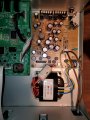
The attached picture is the power supply of the Boss GT-Pro Guitar Amp Modelling Effects Processor. It is over 10 years old. No physical movement, banging around, etc. It just sits in the studio. Power on and off daily over the course of a decade. Here is the problem. It has recently not powered on when I flip the power switch. I have to unplug, wiggle wires, tap the transformer lightly with the butt end of a screwdriver, wiggle the capacitors, etc. Plug back in, flip the switch and it powers on. Very frustrating, as it's functionality is 100% tested good during performance. I have tested the power switch with a continuity meter. I have tested the wiring with a continuity meter. All okay with no shorts. I have used a magnifying glass to inspect for obvious component failure tell tells...all okay. I have not pinned down yet exactly what event will get it to reengage, as I have only done this cover off tweaking process about a dozen times. A long time ago ('60s), my dad showed me how to temporarily fix a failing flyback transformer on a TV without knocking myself across the room due to current. He would hit it with the butt end of a screwdriver, it would reengage, and all was well again. You could keep doing this until it just died. Don't understand why, but it was a temp fix. I am suspecting the same thing with this power supply, but I just don't know. I have NO SCHEMATICS FOR THIS UNIT. I do have some knowledge as I have built motherboards, embedded systems, firmware, assembly language, etc., but I am not an EE. I do have good tools, such as a good meter, probes, oscilloscope, etc., but without a SCHEMATIC, I am lost as I am not an EE. I even have a LOT of components such as capacitors (such as shown in the picture), resistors, gates, etc...as I cobble a lot. I am at the end of my troubleshooting prowess.

Forum, what in your opinion would be the best way to troubleshoot this problem, I REALLY want to fix this because I LOVE this unit and it works (when the power is on :). I already looked for parts such as the power supply and cannot find one. I would have bought it and replaced it component by component, but to know avail. I even thought of testing the voltage outs and building my own, but I would need a senior advisory to do that (I know what blue sparks are and their result :)

Any advice from you all would be GREATLY appreciated. Thank you, in advance, for your opinions.

Best
 

Attachments

JoeJester

Joined Apr 26, 2005
4,390
If your restoring operation by wiggling and tapping different area's of the power supply, you should unplug it, turn the power supply over, and look for defective soldering joints.

Take a picture of the underside of the power supply and post it.
 

Thread Starter

burksfamly

Joined Mar 12, 2020
20
If your restoring operation by wiggling and tapping different area's of the power supply, you should unplug it, turn the power supply over, and look for defective soldering joints.

Take a picture of the underside of the power supply and post it.
Okay...that will have to wait untill the weekend...in the interim...based on your experience, what does this symptom most likely point to...e.g., I just find it improbable that the R-core transformer would go bad with the type of use described...it has just been sitting there in one location...powered on then off...no physical movement...
 

JoeJester

Joined Apr 26, 2005
4,390
from your description, you can have a defective solder joint, a crack in a run, etc. the fact you hit the transformer doesn't mean you didn't vibrate elsewhere.

you need to narrow down what you wiggled to get it to come back on. That would be where you can start. Else it's just you posting a picture and the members here attempting to identify defective solder joints from that picture.

Try measuring a voltage from the power supply and then go about tapping. Repeat for each of the output voltages until you lose one.
 

Thread Starter

burksfamly

Joined Mar 12, 2020
20
Small update.
Had to wiggle wires, bump transformer, etc. again to get the power to engage when the rocker switch is flipped.
The update I should mention is that this happens when the unit is not moved or budged at all. Not a vibration.
I just find it odd that once it "cools down overnight and a day" (it doesn't produce heat much) that it wont power on. Then it will after bumping the transformer, wiggling wires, etc. It is on now...and I can go over and turn it off, count to 20, and turn it on again...and repeat...not problem...but if it is overnight the next day I can assure you that it wont turn on.

This weekend I will try to isolate the action that actually engages the unit when the problem occurs...but this will be a timely process as it has to cool down overnight to happen again...I will also look for broken connections and cold solder joints...but based on my experience, this will not be it...I have repaired cold and fused solder joints on things like microwaves that have given up after 20 years of power on power off...saved some bucks...but this problem unit does not draw enough power to do this, and is high quality...old, but quality...my get tells me it is the R-core or one of the capacitors etc...without a schematic, does anyone know how to test an insitu capacitor, there are a lot of them on the board, how about the power supply...
 

eddwhatley

Joined Sep 16, 2014
4
Sir burksfamly . . . . .et al . . .

Take note of the illustration of the power supply and you can see that I have partitioned off all of its AC power aspects within a
YELLOW box area .
Since you are having either a works or works IF you jump start / HIT IT ! in its sweet / (sore) spot I would tend to think that you are having a connectivity pronlem within this area . . .either a push on connetor or plug or a sometimes "floating " connection within a solder blob .

ROUTING . . . .
AC Line power comes in at the top and passes down the board until the hot side receives a fusing and the hot line is then passed off to the two BROWN lines to the power switch.
You can see all of the missing components layout symbolizations, they were related to a switch mode power supply design . . . alas this design with its toroidal power transformer and a resultant linear design. They only used the blue disc ceramic type "CX" across the power switch to snub the back EMF spike at power turn off, and thus minimize any spark induced erosion of its contacts.
Then there is the secondary of the power transformer and its RED and ORANGE windings and the use of an ohmmeter should reveal if the BLACK is being the center tap of either the RED and ORANGE windings.
With those winding configuration then being figured out, one could expect each winding to be creating a DC supply voltage , and the winding with a tap could provide 2 more.
Those secondary windings then octopii out and can go to two small FWB rectifiers as the GREEN square units and the HEAVIEST FWB as the BLUE square unit.
Additionally we can see 4 round cased bel FUSE units as RED squares.
Way back on the heat sinks in the rear are two power IC's on the left as VIOLET triangles .
Now, might these be two 3 terminal regulator units akin to 7805 or 7812 units ?
The right heat sink receives two TO-220 cased power transistors as ORANGE triangles . . . . more akin to the task of being series pass transistors for the large and major FWB power supply portion.

THESE are all INDIVIDUAL and SEPARATE power supplies, so I really think that your fault being experienced is related to the initially related YELLOW boxed in area.

LOGICAL INITIAL TEST . . . .

After figuring which winding the BLACK wire is tied into . . . . . . get your unit operating . . . .by your special gyrating body antics . . . .spiritual incantations . . . .hand movements . . . . .or just downright WHACK the unit.
Once it has come on and will likely stay 100% operational for 2 hours or 2 weeks continually, take voltmeter in hand and place in AC Voltage mode, probably 100V scale, to be safe, unless the unit is autoranging.
Then you log down the ORANGE to ORANGE and RED to RED AC voltages and the BLACK to whichever the winding is, that it is associated with, for its two readings.
THEN you power down and do the wait and sit "cool down-Stone Cold Steve Austin " procedure until that unit then does its no come on for you situation.
THEN . . . I am of the belief that those voltages will be missing, on your doing a retest, while the unit is being in that inoperable state..
Suggesting . . . . . that one must then do a VEWY-VEWY- VEWY CLOSE inspection of ALL of the connections within the YELLOW boxed in area.

ILLUSTRATION . . . . .

BOSS POWER SUPPLY.png

73's de Edd . . . . .


My doctor told me that jogging could add years to my life. He was absolutely right— I definitely feel ten years older already.

.
 
Last edited:

Dodgydave

Joined Jun 22, 2012
11,284
I would get a DVM and measure the output of the Transformer wires, red, oranges, and black, ideally at the bridge rectifiers ~~ pins,, ( marked with a Green and Blue square)
 

Thread Starter

burksfamly

Joined Mar 12, 2020
20
from your description, you can have a defective solder joint, a crack in a run, etc. the fact you hit the transformer doesn't mean you didn't vibrate elsewhere.

you need to narrow down what you wiggled to get it to come back on. That would be where you can start. Else it's just you posting a picture and the members here attempting to identify defective solder joints from that picture.

Try measuring a voltage from the power supply and then go about tapping. Repeat for each of the output voltages until you lose one.
Thank you so much...I will use this info but may take time to get back. Other priorities at moment stemming from CV19.
 

Thread Starter

burksfamly

Joined Mar 12, 2020
20
Sir burksfamly . . . . .et al . . .

Take note of the illustration of the power supply and you can see that I have partitioned off all of its AC power aspects within a
YELLOW box area .
Since you are having either a works or works IF you jump start / HIT IT ! in its sweet / (sore) spot I would tend to think that you are having a connectivity pronlem within this area . . .either a push on connetor or plug or a sometimes "floating " connection within a solder blob .

ROUTING . . . .
AC Line power comes in at the top and passes down the board until the hot side receives a fusing and the hot line is then passed off to the two BROWN lines to the power switch.
You can see all of the missing components layout symbolizations, they were related to a switch mode power supply design . . . alas this design with its toroidal power transformer and a resultant linear design. They only used the blue disc ceramic type "CX" across the power switch to snub the back EMF spike at power turn off, and thus minimize any spark induced erosion of its contacts.
Then there is the secondary of the power transformer and its RED and ORANGE windings and the use of an ohmmeter should reveal if the BLACK is being the center tap of either the RED and ORANGE windings.
With those winding configuration then being figured out, one could expect each winding to be creating a DC supply voltage , and the winding with a tap could provide 2 more.
Those secondary windings then octopii out and can go to two small FWB rectifiers as the GREEN square units and the HEAVIEST FWB as the BLUE square unit.
Additionally we can see 4 round cased bel FUSE units as RED squares.
Way back on the heat sinks in the rear are two power IC's on the left as VIOLET triangles .
Now, might these be two 3 terminal regulator units akin to 7805 or 7812 units ?
The right heat sink receives two TO-220 cased power transistors as ORANGE triangles . . . . more akin to the task of being series pass transistors for the large and major FWB power supply portion.

THESE are all INDIVIDUAL and SEPARATE power supplies, so I really think that your fault being experienced is related to the initially related YELLOW boxed in area.

LOGICAL INITIAL TEST . . . .

After figuring which winding the BLACK wire is tied into . . . . . . get your unit operating . . . .by your special gyrating body antics . . . .spiritual incantations . . . .hand movements . . . . .or just downright WHACK the unit.
Once it has come on and will likely stay 100% operational for 2 hours or 2 weeks continually, take voltmeter in hand and place in AC Voltage mode, probably 100V scale, to be safe, unless the unit is autoranging.
Then you log down the ORANGE to ORANGE and RED to RED AC voltages and the BLACK to whichever the winding is, that it is associated with, for its two readings.
THEN you power down and do the wait and sit "cool down-Stone Cold Steve Austin " procedure until that unit then does its no come on for you situation.
THEN . . . I am of the belief that those voltages will be missing, on your doing a retest, while the unit is being in that inoperable state..
Suggesting . . . . . that one must then do a VEWY-VEWY- VEWY CLOSE inspection of ALL of the connections within the YELLOW boxed in area.

ILLUSTRATION . . . . .

View attachment 201963

73's de Edd . . . . .


My doctor told me that jogging could add years to my life. He was absolutely right— I definitely feel ten years older already.

.
Thank you so much for the detailed analytical response. That response reminds me of me when I know something and want to truly help them out my wife is the one that has to shut me down and she tells me to land the plane. I actually understood about half of your response and I feel that I can research the other half to understand completely. BTW I may have found a unit on ebay foe parts but dont want to do yet...I will use this info but may take time to get back. Other priorities at moment stemming from CV19.
 

Thread Starter

burksfamly

Joined Mar 12, 2020
20
I would get a DVM and measure the output of the Transformer wires, red, oranges, and black, ideally at the bridge rectifiers ~~ pins,, ( marked with a Green and Blue square)
Thank you so much...I will use this info but may take time to get back. Other priorities at moment stemming from CV19.
 

MrChips

Joined Oct 2, 2009
30,707
Next time, don't bang on it. You can't fix electronics that ain't broken.
Instead, get out a voltmeter and start looking for lack of voltages.
You want to find out where voltage is present and where it is not present. This will narrow down your search for the fault.
What you don't want is for the fault to go away on its own.
 

Thread Starter

burksfamly

Joined Mar 12, 2020
20
Next time, don't bang on it. You can't fix electronics that ain't broken.
Instead, get out a voltmeter and start looking for lack of voltages.
You want to find out where voltage is present and where it is not present. This will narrow down your search for the fault.
What you don't want is for the fault to go away on its own.
Agree...Im a pretty good hacker but not an EE...it will take time to gain confidence to do your logical suggestion which is very intuitive...very intuitive and just makes sense...I know what blue sparks are and have experienced them on my IoT projs but I cant afford to do it on this unit...plus I dont have a schematic and really cant tell where and what voltages should be present in any given state...I get your response and thank you...will eventually get there...Thank you so much...I will use this info but may take time to get back. Other priorities at moment stemming from CV19.
 

Thread Starter

burksfamly

Joined Mar 12, 2020
20
I would get a DVM and measure the output of the Transformer wires, red, oranges, and black, ideally at the bridge rectifiers ~~ pins,, ( marked with a Green and Blue square)
Thank you so much...I will use this info but may take time to get back. Other priorities at moment stemming from CV19.
 

Thread Starter

burksfamly

Joined Mar 12, 2020
20
Next time, don't bang on it. You can't fix electronics that ain't broken.
Instead, get out a voltmeter and start looking for lack of voltages.
You want to find out where voltage is present and where it is not present. This will narrow down your search for the fault.
What you don't want is for the fault to go away on its own.
BTW...I just saw it...I'm a bithead and LOVE the tag line on your signature...nice! :)
 

djsfantasi

Joined Apr 11, 2010
9,156
Hi! You’ve claimed that nothing has moved. But it has.

Ten years of being powered on daily and powered off at night has made just about everything move. Ten years of thermal shock has stressed solder joints and wires especially the thin wire in the transformer.

In addition, you asked why just turning it on works to fix it sometimes. It’s because other components generate enough heat so that a hair thin crack closes as the metal expands.
 

Thread Starter

burksfamly

Joined Mar 12, 2020
20
Hi! You’ve claimed that nothing has moved. But it has.

Ten years of being powered on daily and powered off at night has made just about everything move. Ten years of thermal shock has stressed solder joints and wires especially the thin wire in the transformer.

In addition, you asked why just turning it on works to fix it sometimes. It’s because other components generate enough heat so that a hair thin crack closes as the metal expands.
Interesting...I understand what you are driving at...I hope to be able to isolate soon...I would liked to buy the exact same transfomer just to exchange and test, but I cannot find the exact one...I even texted the compant in Japan but no reply...I saw an exact unit on ebay but not sure if I want to do that yet...troubleshooting is fun when you have the time...too much going on right now with other priorities...also would be usefull to have a schematic to maybe build my own transformer...possible not probable...if it is the transformer...thanks...
 

MrChips

Joined Oct 2, 2009
30,707
I place my bets that it is not the transformer.
If you do replace the transformer and the problem goes away I guarantee that the problem will come back one day because you didn't fix the problem.

Get out the meter and start looking at voltages. We can guide you when you are ready.
 

Thread Starter

burksfamly

Joined Mar 12, 2020
20
I place my bets that it is not the transformer.
If you do replace the transformer and the problem goes away I guarantee that the problem will come back one day because you didn't fix the problem.

Get out the meter and start looking at voltages. We can guide you when you are ready.
Copy that...
 

Thread Starter

burksfamly

Joined Mar 12, 2020
20
Thank you all for you great comments. I have read and digested your info with a bit of background research.

After reading the comments, I want to hold off physically removing and manipulating the power circuit board until we perform the proposed test below.
My rationale is that if it is a weak link and I manipulate it so it no longer comes on, without a schematic, I will not be able to troubleshoot. IMHO

I would like to propose an initial troubleshooting plan since I do not have a schematic, and I need your assistance for definitive direction.
As you can see below, I have some knowledge (white hat hacker), but have questions and need direction so we are all on the same page.

If you wouldn't mind, would you review the plan, confirm my guesses, and provide any direction. I will synthesis the comments and if no conflicts
are found, then proceed with the test, build a table of test voltages and report back. BTW...the unit has not failed to power on yet, but
chances are it will soon.

PROPOSED TROUBLE-SHOOTING PLAN - Phase I

The objective of Phase I is to document the voltages at key locations when the Boss Gt-Pro Unit is ON and functioning.
In my simple words, what I am doing is developing a baseline schematic of voltages that will be used to test the Unit
when it fails to come on when I depress the rocker switch. We will have a spreadsheet of before and after voltages
at key locations when the unit is functioning and then when the unit will not power on when the rock switch is depressed.
This should provide information, hopefully, on a Phase II plan, which may require removal and inspection of the
underside of the power circuit board.

I have attached a picture with alphanumeric annotations and polarity when known.

AC SIDE (Use my DVM and set to 100VAC - United States power grid)

A) Power cord direct from AC wall outlet. I expect to see 120V across these terminals.

B) Fuse. I expect to see 120V across this fuse.

C) Capacitor. I do not know how to place the probes across these terminals nor what voltage to expect.
I also do not know the polarity of the terminals.

D) Rocker switch. I have already tested continuity on this rocker switch and it is good without noise.
I do not know what AC voltage to expect nor do I know the polarity.

E) Power supply to transformer. I do not know how to place the probes across these terminals E1, E2, E3
to test the voltages. I do not know the polarity. Intuitively, I could guess that the white wire is
nuetral (ground) and the blue wire is hot as well as the yellow wire is hot. The table screened on the
board under the terminasl indicates blue at 100V and yellow at 117V presuming AC. So, I would think
that the black probe of my DVM would go to E3 nuetral and the red probe of my DVM would go first to
E1 to confirm 117V and then to E2 to confirm 100V. That is my guess. Confirmation?

DC SIDE (Use my DVM and set to DC, but range is unknown)

F) The header block on the circuit board (output of the transformer) has five pins. In do not know what
DC voltage range to set my DVM to. I also do not know how to pair F1 thru F5 to benchmark voltages
when the unit is up and operational. I can make an educated guess. F2 appears to be DC ground. So,
I would place the black probe of my DVM on F2, and move my red probe to F1, F3, F4, and F5 separately
and pull DC voltage readings for 4 pairs: F2-F1, F2-F3, F2-F4, F2-F5. But that is just an intuitive guess.

Thank you for your assistance.BOSS POWER SUPPLY.png
 

MrChips

Joined Oct 2, 2009
30,707
I have not read all of your test procedures thoroughly but it appears that you do need some assistance.

1) While having a circuit schematic is very useful, when none is available you have to learn to work without one.

2) As I mentioned before, I would not wait for the unit to be working in order to localize the fault. You want to find the fault while it is not working. Granted, you may be inexperienced at trouble shooting electronics and would prefer to have a baseline to compare. Sometimes this is desirable but I believe it is not necessary in this case.

3) Your assumption in test (B) is not correct. You will not expect to see 120V across the fuse.

With that last observation alone, I would suggest that you STOP right there and proceed no further. Wait for someone with the appropriate knowledge and experience to guide you through with LIVE power testing.

Without proper care you will either kill the unit or kill yourself which would be both unfortunate. If we don't hear back from you we will assume the latter and may you R.I.P.
 
Top