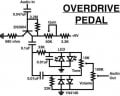
If there is any misunderstanding about my question all I need to know is if the two LED's and two 1N4148's are directly connected to each other or does the one simply run straight to ground?
I dislike schematics that don't have dots at the connection junctions.
It leads to ambiguity as this schematic has, since as shown, the strict convention is that only the left diodes are connected to ground.
I dislike schematics that don't have dots at the connection junctions.
It leads to ambiguity, as this schematic shows, since the strict convention is that only the left diode is connected to ground as shown.
I dislike schematics that don't have dots at the connection junctions.
It leads to ambiguity as this schematic has, since as shown, the strict convention is that only the left diodes are connected to ground.
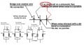
I make my drawings with three different conventions: The first is where no wire crosses OVER another unless it is indicated by an arched bridge over it. The second is where the layout of the circuit is so that EVERY junction of the wires drawn are connected. The third is one I rarely use and that's to put dots at junctions.
Starting with Tony's post, I recommend not to use his third example, wires crossing and connecting with a dot. Better to offset one wire so the group now is two T connections (zero ambiguity) with dots on both (belt and suspenders).
That's what the drawing shows: one LED anode, and one LED cathode connected to each other and "ground", but probably the actual components are merely connected to the common "ground" plane.
That shouldn't be difficult to verify.
The drawing style is kind of lame, but unfortunately common.
Starting with Tony's post, I recommend not to use his third example, wires crossing and connecting with a dot. Better to offset one wire so the group now is two T connections (zero ambiguity) with dots on both (belt and suspenders).
Everyone has their preference. Of my drawings the one I most often use is the fourth drawing (the right most drawing). The second most used is the second drawing from the left. The reason I use the second one at all is because sometimes you have to draw a schematic with lines that must cross. When it comes to dots (the first drawing) I find too often I mis-read them. That's just my preference. If I can draw it without lines crossing then I do. If I must show lines that do not intersect (connect) then I use the bridge. It's what I learned way back in high school, and yes, they had high schools way back then.
Learning electronics in the 50's, as I recall the first EIA convention was to 'bridge' crossing wires, and a dot at ALL connecting wires. Four connections at a dot was acceptable.
The next official evolution was eliminate the 'bridge' and just cross a wire with a straight line. All connecting wires used dots. I think this occurred in the late 60's or early 70's. The reason cited for the change was the extra time the 'bridge' took to draw (remember, this is before CADD).
The current official practice is no bridge, not dots. Crossing wires are straight lines and only three connections at a single point is allowed (a "T"). If there is need to have more connections, then a 2nd "T" must be drawn.
Personally, I like using a 'bridge' because there is no ambiguity and I haven't seen a poor printing job since reproduction 30's schematics. I try to avoid 4 wires at a single point, but sometimes it just works the best on a schematic. I usually don't use dots except where I have 4 wires meet a single point, which I attribute to my German overkill.
I see you are using a 3904 transistor. It will sound OK but probably not like you really want. If tou can get your hands on a germanium transistor, the results will be more like the Jimi Hendrix Fuzz Face units from the 60's. Using. Germanium transistor will probably involve some circuit component changes. Do some research and check for the old fuzz box circuits and have a look how these were designed.
Interesting. I grew up on the "bridge" approach but modern schematic design programs use the "dot junction" approach so I pretty much moved to that. But, as long as the schematic is clear on what convention is being used, it causes no mental anguish. Also, I like the clarity of the rightmost approach but that isn't at odds with "dot junction" - it's about keeping your schematics as simple as possible which is good no matter what convention you use.
My LTspice simulation program uses (square) dots and straight crossings, and I've always used the same convention in my hand drawings.
I've never had a problem with ambiguity using that convention.
All the other responders are right. Junction points should be indicated with dots. This removes any confusion.
if you are planning in building this, I suggest you remove ALL the diodes, LEDs and 4148s. Get rid of everything past the output of the 3904. If you bias the transistor correctly and add the output volume pot on the output of the transistor, you will have all the overdrive you need. If you want to keep the diode arrays, then just use the LEDs. They will make your distortion pedal sound better that adding the 4148s. If you want to make the overdrive sound better still, then drop the NPN approach and re do the circuit with a 2N3906. The results will be much more satisfying. You will need to change your circuit, ( pay attention to the power polarity reversal ) but if you check on line for vintage fuzz box circuits, you will see many designs using the PNP approach. Good luck!
A PNP germanium has less leakage than the NPN germanium. It also takes up less substrate area. That is why pretty much ALL very early solid state design was based on PNP transistors. Same thing for integrated circuits - less substrate area.
I have not confirmed this, but I have read that a germanium transistor has a 'softer' clipping than a silicon transistor. For guitar use, that can cause a more pleasing sound (for high fidelity you don't want any clipping at any time). The 0.3V vs. 0.6V turn on threshold really has nothing to do with it because the same collector current can be reached by altering the bias and input signal level.
I built this up last night & I think it sounds like crap. The only difference is that I buffered the output of the tone pot & ran it straight into a headphone amp.
I thought the idea seemed interesting, distorting the highs & lows separately then blending them back together, but it was a one-trick pony to me. No variation in the sound.
I built this up last night & I think it sounds like crap. The only difference is that I buffered the output of the tone pot & ran it straight into a headphone amp.
I thought the idea seemed interesting, distorting the highs & lows separately then blending them back together, but it was a one-trick pony to me. No variation in the sound.
Yeah I agree. The sound wasn't great. I was just after a simple diagram to build a distortion pedal and in turn that's what I got. I'll be tackling more complex circuits in the future.
I hesitate to mention this but have you looked at the PJRC teensy and their audio board? Very sophisticated transforms can be done easily with their audio library. They have a very nice tutorial. Not dirt cheap but around $35 for both a teensy 3.2 and the audio board.

 Facebook
 Google
 GitHub
 Linkedin