Help with circuit

bertus

Joined Apr 5, 2008
22,923
Hello,

The part you show will work with a 24 Volts solenoid.
What the rest of the circuit will do, we can not tell you.
(there seems to be more).

Bertus
 

wayneh

Joined Sep 9, 2010
18,104
I need to get this circuit to work at 24 volts. Will the parts work or will I need to change some.
In case it wasn't already clear, you don't want to use a 12V solenoid in a 24V circuit.

Depending on the unseen parts of the circuit, the 1KΩ resistor might need to be a higher value.
 

BR-549

Joined Sep 22, 2013
4,931
I do not understand what you are asking. There is a supply voltage. And there is a component voltage.

What are you asking? ARE you going to change a component.......or are you changing the supply voltage????
 

Thread Starter

waltztj

Joined Oct 12, 2018
7
I do not understand what you are asking. There is a supply voltage. And there is a component voltage.

What are you asking? ARE you going to change a component.......or are you changing the supply voltage????
I am changing the supply voltage to 24vdc and the sol to a 24 volt unit I want to know if the existing part will work with 24 v or do I need to change some of them
 

BR-549

Joined Sep 22, 2013
4,931
In that case you will need to study optocoupler, transistor and new solenoid data sheets........for voltage and current specs. It will depend if the opto and transistor can supply needed voltage and current for new solenoid unit. You might luck out and only need a resistor change.
 

danadak

Joined Mar 10, 2018
4,057
How much current does the solenoid draw ? What is its DC ohmic coil
resistance ?

In order to saturate the BD137 you should drive its base with 1/10 the
current flowing thru its collector. Datasheet says for 1/2 A collector load
you should drive 50 mA into the base.

Base R = (V12v_supply_min - Vcesat_optocoupler_output) / ( Icollector_BD137 / 10)

Regards, Dana.
 

Sensacell

Joined Jun 19, 2012
3,784
Leakage current through the opto may cause current to flow through the transistor, even when it's off.

Add a 10K K resistor from base to emitter, that will prevent leakage from turning the transistor on.
 

Thread Starter

waltztj

Joined Oct 12, 2018
7
Leakage current through the opto may cause current to flow through the transistor, even when it's off.

Add a 10K K resistor from base to emitter, that will prevent leakage from turning the transistor on.
Thanks
I have more info ….the sol is 24 v at 4.8 watts it will be on for no more than 50 milliseconds at a time. This is for a high speed drip machine.
 

Thread Starter

waltztj

Joined Oct 12, 2018
7
Question.
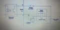
I applied 24 volts to the power supply and I got 24 volts at the opticoupler connection point is that normal. I did not have the coupler in the circuit.
I don't want to blow up anything
 

John_2016

Joined Nov 23, 2016
55
why don't you just try it?

if no 24V solenoid, would it make sense to get another 12V solenoid and add it in series to the currently fitted one?
 

MisterBill2

Joined Jan 23, 2018
27,511
Here is the rest of the circuit and the sol will be 24 volts
The circuit as shown would also function the same on 24 volts, except that the 1000 ohm resistor should be increased to probably 2000 ohms, or the more standard value of 2200 ohms, (red, red, red), to avoid having excessive base drive to the transistor.
 
Top