Help with an ESC schematic

Thread Starter

joelsurfer

Joined Apr 25, 2022
8
Hi everyone! I need help with the following:
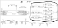
I want to design an ESC (for a three-phase brushless motor) and I am looking at a schematic that does not explain the reason for the use of switching cells in parallel. ESCs often have 6 MOSFETs of the same type, but this one has 12, 4 per phase (2 P-type above and two N-type below), with the switching cells in parallel as shown in the image. Does anyone really know why it does this? The boy says "For greater safety and to reduce the effort of the components, two elementary cells are placed in parallel for each phase of the motor." The only thing I can think of is that you implement it to divide the current that each MOSFET has to support.
Thanks for any possible answers!
 

Attachments

MisterBill2

Joined Jan 23, 2018
18,568
Depending on the loads and the rating of the mosfets, it could be providing redundancy, in that it could continue to drive if one device failed open. Without some small series resistors in the source leads, like is done with parallel bipolar transistors, there will be no forced load sharing.
It might be that the designer is attempting to use devices with inadequate current ratings, in which case it is going to have a major failure in the near future.
The problem is that with switching devices in parallel without a means to make them share the current, it is not likely that they will share the current. So there is a problem of no sharing. Quite a serious problem, if the ratings are not adequate .
 

Thread Starter

joelsurfer

Joined Apr 25, 2022
8
Thank you!! The thing is that I am doing my final year project at the university and I want to know if it would be appropriate to implement this circuit for a current of 30A (I know that to withstand that current, more powerful MOSFETs may be needed). I am attaching the final circuit with drivers on which we would base it, but what I don't know is if it would really be interesting to have those MOSFET cells in parallel or we could achieve it simply with one MOSFET cell per phase.

Depending on the loads and the rating of the mosfets, it could be providing redundancy, in that it could continue to drive if one device failed open. Without some small series resistors in the source leads, like is done with parallel bipolar transistors, there will be no forced load sharing.
It might be that the designer is attempting to use devices with inadequate current ratings, in which case it is going to have a major failure in the near future.
The problem is that with switching devices in parallel without a means to make them share the current, it is not likely that they will share the current. So there is a problem of no sharing. Quite a serious problem, if the ratings are not adequate .
 

Attachments

jojoAI

Joined Oct 8, 2021
5
I would recommend to plan a resistor in series of each gate and also a capacitor for each gate (if not needed you can use a 0 Ohm resistor). I don't know if you have losses while switching the MOSFETs but you should check it because theses losses would only be seen by one MOSFET (because they will never turn off a the realy same time). The only improvment of using more than one MOSFET is the smaler RDs_on value. If money doesn't play a role you could also use a MOSFET with a really low RDs_on so that you don't need 2 or more of them in parallel.
 

Alec_t

Joined Sep 17, 2013
14,329
Apart from current-sharing, another reason for having parallel FETs could be heat-dissipation sharing, dependent on device packaging, mounting, heat-sinking availability and environment.
 

MisterBill2

Joined Jan 23, 2018
18,568
Both JOJO and AL T make good points, although I would not add any capacitors . But a separate resistor for each gate is a good idea. AND you do need to examine the specifications as far as current rating for each device. And probably a lower value of the series resistor because slow switching will greatly increase the power dissipation in the devices. The applications literature for the driver devices may address that consideration.
Sharing the heat load among devices does improve the product lifetime, but it is seldom considered in designs where minimum cost is the primary motivation. So heat spreading can be mentioned in the design discussion presented with this project. At 30amps per phase the disipation will be enough that adequate heat sinking is required, and once again the load versus the device ratings needs to be considered, along with the safety margin, actual current versus specified max repetitive current.
One other thought is about preventing "shoot-thru", that condition where both transistors conduct at the same time. Hopefully the drivers prevent that possibility, but I have not investigated it by examining the specifications of the drivers. It seldom causes problems in simulations, but in the real world it is usually fatal to the transistors.
 
Last edited:

Alec_t

Joined Sep 17, 2013
14,329
When reading datasheets to select MOSFETs, bear in mind that they often specify current ratings for the (unlikely) condition that the MOSFET case temperature is kept down to 25°C. Check the de-rating factor for higher temperatures.
 

Thread Starter

joelsurfer

Joined Apr 25, 2022
8
Well thanks to all but finally I´m using another circuit, can anyone help me with the schematic part of the BEMF voltage divider? Thanks. What do you think A0, A1, A2 and D6 are doing? I think that D6 detects when it´s a 0 crosing and A0, A1, A2 detect during all the time if they´re floating or if they are active phases. So then, knowing with phase is floating and knowing how the other two phases are, we can know wich is the next step sequence. Schematic.png
 

MisterBill2

Joined Jan 23, 2018
18,568
While the circuit looks reasonable, at least without a detailed analysis to verify component selections and resistor values, correct operatio will depend on a whole lot of software being present. That is, the system certainly must have the specific code to go with all of those connections.

So for this system the code is a large part of the project!!
 
Top