THis is my understanding of the internal motor wiring. The main inding is in two equal parts.One is between A1 and A2. the other is between A3 and A4. So the wau the links are fitted they are in parallel. (For 115 volt working.) Withe the single link in the position for high voltage the two windings are in series. I think the top left terminal in the picture in post #11 is connected internally via a centrifugal switch to terminal A1. (This may be a direct link and the centrifugal switch is connected directly in series with the start winding.) The two wires Z1 ans Z2 are the start winding. This will allways be supplied with 115 volt. This is directly from the supply with the low voltage strapping. With the two parts of the main winding in series for the high voltage strapping the main winding is working like an auto transformer providing 115 volts for the start winding. There should be another two wires comong from inside the motor. (These are Z1 and Z2 the ends of the start winding.)
Do the two ires that are not connected to anything look like the go out of the motor up to the switch unit.
I would get an ohmmeter and measure the resistance between all combinations of A1, A2, A3, A4.
Hopefully, you should find A1-A2 with one resistance value, and A3-A4 with another resistance value.
Perhaps there should be no connection between the two pairs.
You will need some proper reversing contactors for the final hook-up, small relay will not cut it for reversing the actual motor power.
As suggested, I would remove all strap links on the motor and measure the winding connection coming out of the motor.
I assume you want to use the LV, 240vac connection?
That is assuming it is a 240v/420v motor?
elioti, Can you tell us if the motor is from the US /Canada or Europe? I have only heard of dual voltage motors in the US and Canada. I have only seen 3 phase motors rated for 420 volts in Europe. Also I don't think the green/yellow wire is used in the US. It is used as the earth connection in Europe.
You will need some proper reversing contactors for the final hook-up, small relay will not cut it for reversing the actual motor power.
As suggested, I would remove all strap links on the motor and measure the winding connection coming out of the motor.
I assume you want to use the LV, 240vac connection?
That is assuming it is a 240v/420v motor?
Thanks yes, it's a 240v motor and use a 240v supply. Appreciate your time in replying, I've a good multimeter, how would I measure the windings please.
I would get an ohmmeter and measure the resistance between all combinations of A1, A2, A3, A4.
Hopefully, you should find A1-A2 with one resistance value, and A3-A4 with another resistance value.
Perhaps there should be no connection between the two pairs.
elioti, Can you tell us if the motor is from the US /Canada or Europe? I have only heard of dual voltage motors in the US and Canada. I have only seen 3 phase motors rated for 420 volts in Europe. Also I don't think the green/yellow wire is used in the US. It is used as the earth connection in Europe.
Hi, thanks, is it dual voltage? The motor only had Brown wires , is random wires that are connected to these that don't help sorry. I bought it second hand in the UK
Thanks everyone, a clever bunch! And I'm sounding a bit daft probably. I can do boat electrics but not sure about this. So perhaps I should check the reading of the windings of the two wires already connected to it? And the windings from the two wires that were connected but are no longer? Then come back to you?
If it ran by a simple on off switch, in theory, couldn't the start and run terminals be connected together then? As was powered by the same single source.
I can work out from the picture, the connections with yellow crimps ( that were connected and now not) are z1 and z2, guess why needs help starting. So should connect these up somewhere? Could I not put them to 240v, one to earth other to positive ? Not sure if can and which way around appreciate I need a proper control, not sure what I need though it did work for years.
THis is my understanding of the internal motor wiring. The main inding is in two equal parts.One is between A1 and A2. the other is between A3 and A4. So the wau the links are fitted they are in parallel. (For 115 volt working.) Withe the single link in the position for high voltage the two windings are in series. I think the top left terminal in the picture in post #11 is connected internally via a centrifugal switch to terminal A1. (This may be a direct link and the centrifugal switch is connected directly in series with the start winding.) The two wires Z1 ans Z2 are the start winding. This will allways be supplied with 115 volt. This is directly from the supply with the low voltage strapping. With the two parts of the main winding in series for the high voltage strapping the main winding is working like an auto transformer providing 115 volts for the start winding. There should be another two wires comong from inside the motor. (These are Z1 and Z2 the ends of the start winding.)
Do the two ires that are not connected to anything look like the go out of the motor up to the switch unit.
Hi Les, thanks. It's running off 240v. The two wires did go to the switch unit like you say, believe are z1 and z2 ( ones with yellow crimps on). Appreciate your help
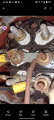
This morning I could open the pictures in post #12. It looks like there are two taped joints. I suspect that these are the Z1 and Z2 wires being extended back to your switch unit. Am I correct? I think I can see 5 wires going through the cable exit hole in the motor connection box, (black, blue, green/yellow, and two brown.) Am I correct.
can you do the following.
1 Move the taped joint on the blue wire so I can see underneath it and see what wire or wires are connected to the other side of the joint.
2 Take a picture from further away so I can see where the brown wire from the other tape joint goes to.
3 Trace out a schematic (Circuit diagram.) of your switcing unit.
I suspect this equipment is in the UK so I think the green/yellow wire is an earth wire. Can you check that it is connected to the earth on the incoming supply. If this is so then it should NOT be connected to the terminal block in the motor connection box. It should be connected to the motor frame.
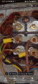
Hi again Les, I remember the tapes wires you mention go straight into the motor to the windings, not connected to the joints unfortunately. They're not z1 or z2, can tell if zoom in that the wires that have the yellow crimps on, black and earth coloured wire ( bottom right, mid left) go to z1,z2, and these are the wires that were connected somewhere but are not now. Can see part of a Z on the picture if zoom in. What doesn't help is that my father likely has used any old colour wire, helps confuse it all. Again, pretty sure the two loose wires go to z1 and z2. Thanks again
This morning I could open the pictures in post #12. It looks like there are two taped joints. I suspect that these are the Z1 and Z2 wires being extended back to your switch unit. Am I correct? I think I can see 5 wires going through the cable exit hole in the motor connection box, (black, blue, green/yellow, and two brown.) Am I correct.
can you do the following.
1 Move the taped joint on the blue wire so I can see underneath it and see what wire or wires are connected to the other side of the joint.
2 Take a picture from further away so I can see where the brown wire from the other tape joint goes to.
3 Trace out a schematic (Circuit diagram.) of your switcing unit.
I suspect this equipment is in the UK so I think the green/yellow wire is an earth wire. Can you check that it is connected to the earth on the incoming supply. If this is so then it should NOT be connected to the terminal block in the motor connection box. It should be connected to the motor frame.
Hi again, a zoomed in picture, can tell bottom right and middle left shows "Z". The earth and black wires are the ones that were connected but now not. The fith brown cable you mention, I'll check later but think goes nowhere as only 4 were connected. Thanks
 Facebook
 Google
 GitHub
 Linkedin


")