Facebook
 Google
 GitHub
 Linkedin
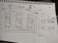
The black and earth colour wires exit the motor connector box. (I assume to the switch unit.) Z1 and Z2 are two wires that come from inside the motor. (The ends of the start winding.) If you look at the picture in post #1 you will see that they would normaly be connected terminal A2 and the unmarked bottom right terminal. The note on the left of the picture tells you to swap them over to reverse the direction of the motor. If the two wires that are taped up are just the ends of two wires from inside the motor and not connected to anything then I don't see how it could have ever worked.
Edit. Where I said "the unmarked bottom right terminal" I should have said terminal A1. (I had seen the letter Z aginst the the bottom right terminal and assumed it was Z2)
Les.
Edit. Where I said "the unmarked bottom right terminal" I should have said terminal A1. (I had seen the letter Z aginst the the bottom right terminal and assumed it was Z2)
Les.
Last edited:
")