 Facebook
 Google
 GitHub
 Linkedin
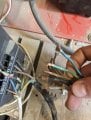
I'm trying to bypass this switch between my 3 phase converter and the motor (for a belt grinder in my workshop)
however I'm unsure how to connect the blue neutral wire
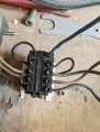
I assume I can just bypass the switch connecting the green, grey, black and brown wires to their counterparts on the converter however I don't know where to connect the blue wire.
In the second photo you can see the connections in the switch I intend to bypass, the blue not having a counterpart after the switch
Any help would be greatly appreciated.
however I'm unsure how to connect the blue neutral wire
I assume I can just bypass the switch connecting the green, grey, black and brown wires to their counterparts on the converter however I don't know where to connect the blue wire.
In the second photo you can see the connections in the switch I intend to bypass, the blue not having a counterpart after the switch
Any help would be greatly appreciated.
Attachments
-
 2.3 MB Views: 38
 -
 6.2 MB Views: 39


