 Facebook
 Google
 GitHub
 Linkedin
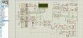
hi every one i am a new user of optocoupler pic817 and for my pwm based h-bridge driving circuit i am using it.. is it a right choice for this circuit?...or should i need to replace it with some other package?
one more thing that i want to clear is,currently i am using emiiters output which is being further fed into buffer . so what if i take output from collector?
my circuit diagram is given in attachment
one more thing that i want to clear is,currently i am using emiiters output which is being further fed into buffer . so what if i take output from collector?
my circuit diagram is given in attachment
Attachments
-
 366.8 KB Views: 35


