Help Please. Pump control with a Shelly

Thread Starter

greypelican

Joined Aug 9, 2026
5
Hello,
I am only a DiYer and not qualified engineer but I'm hoping to get some help to resolve a problem that's really bugging me.

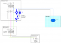
I have a rural property that benefits from a bore hole for water service. For many years the 'manual' circuit has been satisfactory. Power runs from an mcb through to a contactor. A three way switch allows isolation, manual or automatic filling of a water tank according to the position of it's float switch. See BoreHoleWiring.pdf attached.

I now wish to incorporate a Shelly controller into the circuit to allow for remote activation. MainWaterSchematic.pdf is the schematic.
The problem that I am suffering from is that when the float switch energizes for the first time, the contactor sends the Live to the Shelly SW terminal and the pump is activated as expected BUT when the water level reaches it's high point, the contactor remains on. (As if the contactor is stuck on but is not the case as I have tested and it switches on and off as desired). Also the float switch is proving good. It was one of the first items I replaced suspecting it as defective.
No mcb has 'tripped'. no wires shorted out, no bangs or fires.
Clearly there is something that is beyond my comprehension and I'm hoping dear reader that you can offer some help.
 

Attachments

ronsimpson

Joined Oct 7, 2019
4,791
Is the pump three phase 220V? Is the L on the Shelly the same as one of the phases on the top circuit breaker?
I have the float switch not connected to "power" or Contactor" but connected directly to the Shelly L to Switch. I don't see the need for the small contactor.
 

Thread Starter

greypelican

Joined Aug 9, 2026
5
Hi Ron,
Thanks for the quick comeback. Yes 3 phase 230v system for the pump. I have 3 phase coming in from the meter into the DP. My other circuits are spread over the three lines for balance. The L to power the Shelly comes from one of the lines but not sure which one. The small contactor below the (now) 2 way switch is to produce a Live to the Shelly SW terminal. When the Shelly detects a Live on SW it energizes the O terminal and thereby gives the main contactor coil its Positive.
 

ronsimpson

Joined Oct 7, 2019
4,791
I do have some Shellys but not many. I use something different.
I am concerned that we don't understand how the Shelly works. I would put a switch on the Shelly Switch to L pins and a light bulb or ohm meter on the I/0 pins and make certain how it works. What I have, there are several different modes that work different. (on=on, off=off) or (on=off, off=on) or (on to off transition = off, off to on transistor = on) or ? I don't remember. Mine acts different (level) verses (transition).

If I wanted to force the pump on, I would put the Shelly at location 1.
If I wanted to stop the pump under all conditions, I would put it at location 2. (Cut the wires.) Open=off
If I wanted to stop the pump only when it is in Auto mode I would put the Shelly at 3. (Cut the wires.) Open=off
1786306570028.png
Do you want to see if the main contractor is on or off using the Shelly?
Do you want to see of the Flout is up or down using the Shelly?
 

Thread Starter

greypelican

Joined Aug 9, 2026
5
Good morning and thanks again for your input.
You have given me an idea to place the Shelly on one side only (the neutral side). I'll have a go later today
and see if it works.
 

MisterBill2

Joined Jan 23, 2018
28,113
I am quite able to read the drawings, they are quite clear enough.
What is totally NOT CLEAR is neither the purpose, nor the function of "The Shelly", which is an item I am not at all familiar with.
What I see as a problem is the switching of the power to the "shelly" device instead of switching the controlled power to the motor contactor.
That statement::
"I now wish to incorporate a Shelly controller into the circuit to allow for remote activation. MainWaterSchematic.pdf is the schematic." is a problem.
The fault is that the float switch should be directly in series with the motor power contacter control, so that when the float switch opens the pump stops, at least whan the switch is in the "auto" position.
The actual purpose of the shelly remote control package is unclear! And i do not know the actual function of it, as I am not at all familiar with the "Shelly" device.
Presently it is connected to totally bypass the float switch control function. THAT is usually an unacceptable control system condition, since it appears to latch on, and remain on, after the "run" command is received.
 
Last edited:

panic mode

Joined Oct 10, 2011
5,195
and yet you decide to meddle and even shout...

you could google it:
https://www.shelly.com/

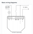
1786368695400.png
0, I : pair of output contact terminals
SW : input for manual switch
L,N: AC power input (home)
12V,N: DC power input (vehicle)

the Shelly in this case is a wirelessly controlled switch (relay). using wireless command from some app it can be turned on and off. it is in a compact hockey puck form factor, making it suitable to install in various places, even behind AC outlet.

i too can read schematics but do not have high praise for shared ones. thing that irks me is the no GND at the motor and using GND wire color as one of phases.
 
Last edited:

panic mode

Joined Oct 10, 2011
5,195
The problem that I am suffering from is that when the float switch energizes for the first time, the contactor sends the Live to the Shelly SW terminal and the pump is activated as expected BUT when the water level reaches it's high point, the contactor remains on.
sounds like you need float switch to stop the pump when high point is reached. for that you need to use normally closed contact of the float switch. in other words, pump can run any time - as long as high water level is not reached. when the high level is reached, float switch contact opens and kills the pump - no matter what. shelly and manual switch may tell pump to run - as long as float switch is ok with that.

something like this:
1786371366972.png
 
Last edited:

MisterBill2

Joined Jan 23, 2018
28,113
I suggest caution with the suggestion in post #8. Mains voltage power to some float switches can lead to a failure mode comnecting power to the float device. Not all float switches are mains voltage insulated. AND not all float switches have adequate contact ratings.
AND, to PM, accusing me of shouting and meddeling: Some words need emphasis, and given that I NEVER use capitals to shout, but rather because they are important, and some float switches are not well insulated.
How is responding to a post being meddeling??
Most industrial applications of tank level control use two float switches, one that opens at the tank upper level to halt the filling cycle, and one that closes at the tank lower level, to start the filling cycle.
I am not familiar with the "Shelly" remote control device, but it is not even close to safe to use the mains neutral for one side of a connection that is also used for low voltage contacts. That is an invitation to a serious shock hazard incident.
 
Last edited:

ronsimpson

Joined Oct 7, 2019
4,791
I suggest caution with
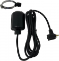
I have several float switches that have worked at 240 for years. This is what I use. It is built to interrupt a 120V power cord.
1786373954872.png
What worries me is the Shelly and Sonoff modules have the "switch" connected to Line not Neutral. The switch is at line voltage.
 

Thread Starter

greypelican

Joined Aug 9, 2026
5
Thank you all for your input.
I have modified the circuit to place the Shelly on the Neutral side jumping the 3-way switch as required to simulate manual on. Leaving the Auto side as is. The contactor and Live feed to the Shelly SW terminal has been removed. It is not ideal as I wanted to know (via the Shelly) when the SW was activated. This now gives me the option to switch on the pump either through the resident home automation system or by 3-way switch in Manual mode.
I did wire in the contactor and Shelly without the 3-way switch but as per the original 'failure' the pump would not power-off when the float switch reached its level. I am assuming that my wiring is creating a neutral pathway which is bypassing the float switch after the pump has started. But I just can't see it.... one wire taking Neutral to the float switch and when closed returning on a second wire.

MisterBill2: very much agree with you about sending a live phase into a container of water.

Thanks again for your time and input.
 

MisterBill2

Joined Jan 23, 2018
28,113
I have several float switches that have worked at 240 for years. This is what I use. It is built to interrupt a 120V power cord.
View attachment 370314
What worries me is the Shelly and Sonoff modules have the "switch" connected to Line not Neutral. The switch is at line voltage.
Switching the line side is correct!
If you switch the neutral side then every section of the circuit past the switch is hot whan the switch is open. That is part of the electrical code. It also makes very good sense.
 

Reloadron

Joined Jan 15, 2015
7,921
I now wish to incorporate a Shelly controller into the circuit to allow for remote activation.
OK being clueless as to what a "Shelly" is I had to Google it. Found the complete line of Shelly products for home automation and just about anything one wants to automate.

Here's the kicker. I did all my searches on my ancient home PC. This system knows nothing of my phone but yet for the past few days my phone gets Shelly advertising. Beats me? Not a big deal and nothing I want to fix, just a curiosity thing I found humorous. They seem to have something for everything and are Amazon Alexis compatible. Nice stuff. :)

Ron
 

panic mode

Joined Oct 10, 2011
5,195
PM, accusing me of shouting and meddeling: Some words need emphasis, and given that I NEVER use capitals to shout, but rather because they are important
using all capital letters in more than one word is commonly seen as shouting. i did not invent that.
you edited your post and now it does have valuable content (cautionary note, float switch interrupting coil power) which originally wasn't there.
Shelly is a very popular brand and even cursory search would instantly clarify any confusion.
and when someone is not familiar with topic, and not willing to research it, that is totally fine. but i would expect them to refrain from commenting.
my opinion of that original post was that it was just attention seeking stunt, hijacking topic, which is why i replied the way i did.
 

Thread Starter

greypelican

Joined Aug 9, 2026
5
Thanks again for your help.
I've taken the suggestions and redrawn my circuit to switch Live.
All working as originally intended.
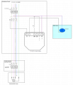
I now have the float switch, when water level is low, feeding live to a contactor, which feeds a Live to the Shelly SW terminal causing it to energise the feed to the main contactor and activates the pump. I can also talk direct to the Shelly to activate the pump on a manual basis and programmatically.
For interest I have attached the schematic.

The one point I would throw out there is that this was not an issue with Shelly. I do have a number of these controllers and am reasonably competent in their operation. More my lack of understanding of the laws of electricity. I am convinced that within my physical wiring, as noted by Post #12, I must have created a Neutral path which maintained a phase on the first contactor thus keeping it active.
 

Attachments

MisterBill2

Joined Jan 23, 2018
28,113
One concern would be the possibility of switching on the pump remotely while somebody was working on it. With some pump systems that could be a safety issue. Since Ihave no information about the pump that is an unknown issue. BUT at one location, while a person was cleaning a large belt driven pump, it was switched on remotely. FORTUNATLY he jumped back when the control contactor operated, so that he was not caught in the drive belt and pulley. THAT would have ripped his arm off.
 

panic mode

Joined Oct 10, 2011
5,195
All working as originally intended.
i have not used Shelly and i do not know your real intent but i would say that this is not right...

most importantly, it does not guarantee that first contactor (one powering pump) will stop the pump when float switch is tripped. and that should be the top priority (permissive).
for that to happen, float switch would need to be wired directly in series with coil of that contactor - no ifs and buts. then contactor would not turn on regardless...
this reduces accidental turning on of that contactor to an absolute minimum number of parts and connections.

everything else is secondary - it doesn't matter if command to run pump is due to local hardwired switch or wireless command, if Shelly fails (stuck on) or if second contactor fails or if there is some other problem. they can try to turn the pump on but as long as float switch and the primary contactor are ok, pump will not run when water level is high.
 
Last edited:

ronsimpson

Joined Oct 7, 2019
4,791
(one powering pump)
I only have a couple of Shellys. I use SonOff. With them there is a way to tell it to power up on or power up off. I think some modules have power up as it was. This is something to look into.

I am now using Hame Assistant to watch all the remote devices. It is good at returning all the devices to the right state after a power failure.
 

MisterBill2

Joined Jan 23, 2018
28,113
Now it is finally clear to me, after reading thru a third time, that the main purpose of including that "SHELLY" device is to alow remotely disabling the water pump. I guess that is reasonable. I have worked on a farm long ago where the only source of safe water was a deep well, with a submersed pump. Certainly the pump controls must have an assured OFF mode available for when it is to be serviced, and for instances where there are water leaks.
For ALL powered equipment it is reasonable to be able to switch it off for whan it is to be serviced. In many areas it is mandatory, for safety, to be have a power-off switc hwithin view of the device being controlled. Yhat makes sense.
 
Top