Facebook
 Google
 GitHub
 Linkedin

Hello,
I am only a DiYer and not qualified engineer but I'm hoping to get some help to resolve a problem that's really bugging me.
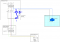
I have a rural property that benefits from a bore hole for water service. For many years the 'manual' circuit has been satisfactory. Power runs from an mcb through to a contactor. A three way switch allows isolation, manual or automatic filling of a water tank according to the position of it's float switch. See BoreHoleWiring.pdf attached.
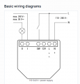
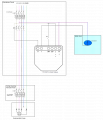
I now wish to incorporate a Shelly controller into the circuit to allow for remote activation. MainWaterSchematic.pdf is the schematic.
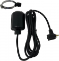
The problem that I am suffering from is that when the float switch energizes for the first time, the contactor sends the Live to the Shelly SW terminal and the pump is activated as expected BUT when the water level reaches it's high point, the contactor remains on. (As if the contactor is stuck on but is not the case as I have tested and it switches on and off as desired). Also the float switch is proving good. It was one of the first items I replaced suspecting it as defective.
No mcb has 'tripped'. no wires shorted out, no bangs or fires.
Clearly there is something that is beyond my comprehension and I'm hoping dear reader that you can offer some help.
I am only a DiYer and not qualified engineer but I'm hoping to get some help to resolve a problem that's really bugging me.
I have a rural property that benefits from a bore hole for water service. For many years the 'manual' circuit has been satisfactory. Power runs from an mcb through to a contactor. A three way switch allows isolation, manual or automatic filling of a water tank according to the position of it's float switch. See BoreHoleWiring.pdf attached.
I now wish to incorporate a Shelly controller into the circuit to allow for remote activation. MainWaterSchematic.pdf is the schematic.
The problem that I am suffering from is that when the float switch energizes for the first time, the contactor sends the Live to the Shelly SW terminal and the pump is activated as expected BUT when the water level reaches it's high point, the contactor remains on. (As if the contactor is stuck on but is not the case as I have tested and it switches on and off as desired). Also the float switch is proving good. It was one of the first items I replaced suspecting it as defective.
No mcb has 'tripped'. no wires shorted out, no bangs or fires.
Clearly there is something that is beyond my comprehension and I'm hoping dear reader that you can offer some help.
Attachments
-
15.7 KB Views: 7
-
32.5 KB Views: 8