Facebook
 Google
 GitHub
 Linkedin
Hello, I am new to the world of building circuits and I came here with high hopes to find someone that could help me bridge the gap between the crystal clear image/idea I have in my mind, and the lack of technical knowledge and vocabulary that I actually hold.
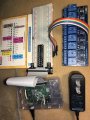
So I guess, ideally, what I'm looking for, is someone that I can explain all the parts I plan on using. Then they will be able to take that list and you can "fritz" or build a schematic (what ever it is called) for me. I have this 40 pin t adapter for the breadboard to my RaspberryPi3 and i cant find a tutorial, it is confusing me. The choosing the correct resistors and capacitors and all that good stuff is just out of my current league and I would be eternally grateful if someone could have grace with me and help a begging man who is just trying to do a good deed for his father.
1x Raspberry Pi3
1x BreadBoard Large
1x 8 channel relay
5x cpu fans
3x DHT22 sensors
2x Soil Moisture meter
2 x Pumps
1x LED
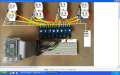