
Help on pgd and pgc io

Thread Starter

PIYUSH SONI

Joined Nov 15, 2013
32
Hii,
I am working on pic 16f1827 with internal osc: 8Mhz
MCLR - disabled, using MIkroC pro & pickit3 programmer. This is the pickit3 connection to the ckt. I have attached the pickit3 programming connection.
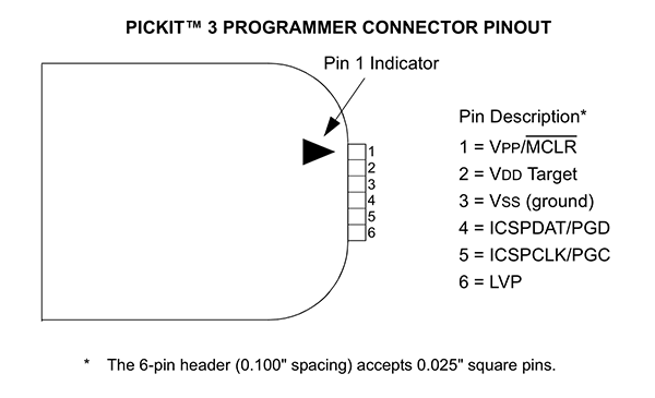

My pickit 3 programmer is working fine only the thing is that i have taken the same pin(PGD & PGC)as IO and also using for programming as per the required connection to programm the ckt using pickit3. I am using PGD & PGC due to the lack of IO pin as per my project.
I am using PGD & PGC as Input to drive LED.

How can i use PGD & PGC pin to make it as IO??
Please Help me.
 

ErnieM

Joined Apr 24, 2011
8,415
I cannot follow what you are saying. The phrase "using PGD & PGC as Input to drive LED" raises more questions then it answers, as inputs typically cannot drive LEDs.

Sharing your schematic is a far better way to have someone not intimately familiar with your specific project to give an answer that makes sense.
 

Thread Starter

PIYUSH SONI

Joined Nov 15, 2013
32
Actually I'm using PGD(ICSPDAT) pin no.13 and PGC(ICSPCLK) pin no.12 as switch(input) to glow the Led(output ). Here as a total I am using 7 input(switches) to glow seven Led(output), out of which 5 inputs are working fine excluding PGD and PGC pin to give output. Only the inputs(switches) through PGD and PGC are not working, I have checked my all switches those are working fine.
Kindly tell me do I need to do some hardware settings to make it work as an input for PGD and PGC pin because they are ICSP pins that I am using for programming or do I need to configure any register to make it work as an Input.
 

Thread Starter

PIYUSH SONI

Joined Nov 15, 2013
32
Hii, Erniem.
I just want to know how can i use pin no-12 & 13 of pic 16f1827 as input. It is an io pin so there must be some way to use it as input.
I am already using this pin while programming through pickit3.
Kindly help me out..
 

tshuck

Joined Oct 18, 2012
3,534
Set the appropriate bits in the corresponding TRIS register...

Edit: see page 117 in the datasheet...
 
Last edited:

MaxHeadRoom

Joined Jul 18, 2013
30,807
It seems you are confusing the two functions, they are completely separate when either programming or program run, (release MCLR).
The restrictions on PGC and PGD is no pullups on either and no caps.
Max.
 
Last edited:

THE_RB

Joined Feb 11, 2008
5,438
When MCLR is raised to Vpp (to initiate programming) the PGC and PGD pins are automatically tristated back to inputs (same as when MCLR is low, ie reset).

You can have pullups or pulldowns on those two pins provided they pullups are weak enough that a standard digital output pin (as used in the programmer device) can override the pullups at high frequencies.

I've used 10k and 22k without a hitch and any resistor higher than that is also fine. :)
 

MaxHeadRoom

Joined Jul 18, 2013
30,807
I was just going by the warning sheet that comes with the Pickit3.

Do not use Capacitors on MCLR - they will prevent fast transitions of Vpp

Do not use Pull ups on PGC/PGD - they will divide the voltage levels since these lines have 4.7k pull down in Pickit3

Do not use capacitors on PGC/PGD - they will prevent fast transitions on data and clock lines during programming and debug communications.

Do not use diodes on PGC/PGD - they will prevent bi-directional communication.
Max.
 

MaxHeadRoom

Joined Jul 18, 2013
30,807
It all depends on your programming board, if you are using something like a Picdem2 etc, and set up the application to run when programming has completed, then if you have pull-ups or pull downs etc on the PGC/PGD lines, then you can have a problem, if you have a stand alone programmer only, and then transfer the Pic to a prototype board then it should work OK.
Max.
 

Thread Starter

PIYUSH SONI

Joined Nov 15, 2013
32
@Max
I am using pickit3 for programming & i am not using any development board for testing. I have my own pcb board on which i am doing this project.
How to do now??
 

MaxHeadRoom

Joined Jul 18, 2013
30,807
@Max
I am using pickit3 for programming & i am not using any development board for testing. I have my own pcb board on which i am doing this project.
How to do now??
So what you are saying is you are trying to program with the application circuit on board?
If so you could put a couple of isolation jumpers on the PRG pins?
Max.
 

THE_RB

Joined Feb 11, 2008
5,438
...
Do not use Pull ups on PGC/PGD - they will divide the voltage levels since these lines have 4.7k pull down in Pickit3
...
Thanks for the info Max.

I don't use the PICkit3 but have used 3 other programmers one being a Microchip device.

A 4.7k pull down on the PGC and PGD lines inside the programmer won't cause a problem, because when driving those two pins the programmer will have a low output impedance digital driver. Usually a small series resistance of about 180 or 220 ohms. That will easily overcome a light pullup like the 10k and 22k resistors I use on PGC and PGD.

It would only be an issue if the PICkit3 has a 4.7k SERIES resistor on its two driver pins, which it wont have because all high speed programmers need to have a lowish output impedance to drive the cabling and target PIC pins etc at MHz speeds. :)


PIYUSH SONI said:
...
I am using pickit3 for programming & i am not using any development board for testing. I have my own pcb board on which i am doing this project.
How to do now??
We need to see the full schematic of your PCB! Including resistor values.

You should be fine with pullup resistors on your PCB on those two pins, provided the pullup resistors are a high enough value. What value are you using?
 
Top





