Facebook
 Google
 GitHub
 Linkedin
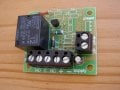
I was wondering if anybody here can help me. I have had some relay circuits built which when a circuit is closed with a button, it triggers the relay which opens a 12v circuit to set off a siren (it has a 5 second timer build in). These are used for our paintball site so when a plastic pad is shot (it has a button behind it) which triggers the siren. They work well a do as they should.
Now the problem?
I would like to use a digital egg timer to trigger the relays so when the timer reaches zero the relay work activate and the siren would go off. However the voltage produced by the egg timers fluctuates between .3 and .5v and is not consistent. This does not seem to trigger the relay circuit. I have asked several people about this with no joy, so I was hoping somebody on here might be able to shed some light.
Thank you all for your time.