Help me figure out this relay circuit?

Thread Starter

jsmith24

Joined Jul 10, 2013
23
Hi all,

I've been pounding my head against this for three hours, and I need fresh eyes. I think what I want to do can be done, it's just eluding me.

This is all 12 volts DC, powered by a standalone SLA battery in the shed.

What I Have:
I have a circuit that raises a door in the morning and lowers it in the evening, using a timer and relays to reverse the direction of the DC motor. Currently, the timer has to stay on all day, then when it turns off it triggers the "down" relay (using the NC contact on the timer). There are limit switches at the top and bottom of the door which shuts off each relay, but the timer's internal relay stays on, and of course, uses power. This is "SchemA.jpg", here:
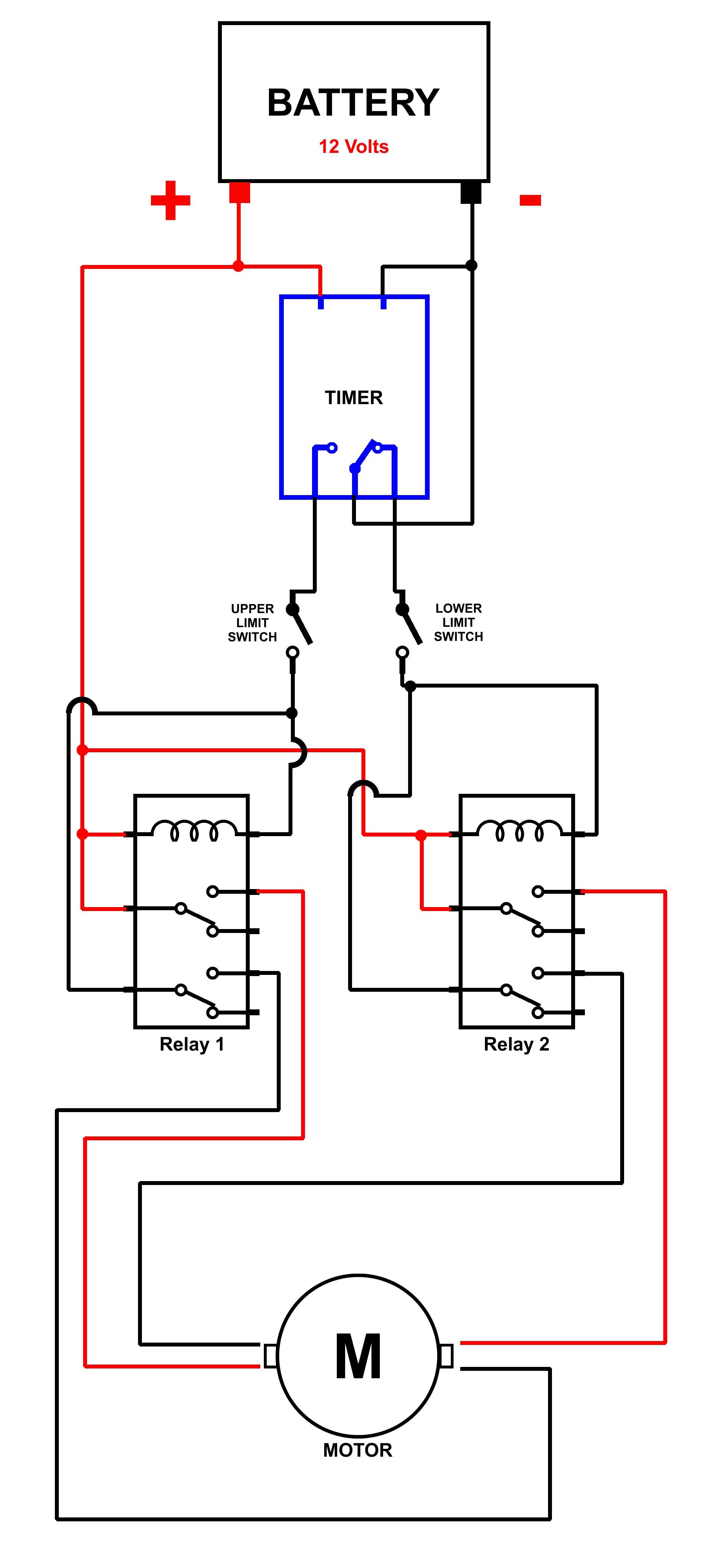


What I Want:
I'd like to have the timer come on for a minute or two, supplying power ONLY for that time while the door raises or lowers. My first thought was that I could have the limit switch run through the unused contacts on the opposite relay, that way, only the relay whose limit switch is closed gets power, the door travels, hits the limit switch and stops. However, once the door begins its travel, the originally "open" switch goes "closed", and as you can see in "SchemB.jpg" below, that means the opposite relay's coil is energized. (The red question marks).


So, is there a way I can do this so that only one relay is energized at a time? The limit switches I used are the three terminal type, with a COM, NC, and NO terminal. The switches currently are using the NC terminal, so that when the door hits them, it breaks the circuit.

Any suggestions are appreciated.

Jack
 

MikeML

Joined Oct 2, 2009
5,444
The timing circuit has to be continuously powered throughout the 24 hour day, otherwise it will lose time reference. The only improvement would be to make the timer so it has two (non-relay) outputs: one to indicate direction, the other to have an output that is slightly longer than it takes the door to make its cycle.

Alternatively, one timer output could be asserted for the same duration as above in the morning, and the other would be asserted in the evening.

Your problem stems from the timer you picked...

How about using a solar detector to make the thing self-synchronizing?
 

Thread Starter

jsmith24

Joined Jul 10, 2013
23
The timing circuit has to be continuously powered throughout the 24 hour day, otherwise it will lose time reference. The only improvement would be to make the timer so it has two (non-relay) outputs: one to indicate direction, the other to have an output that is slightly longer than it takes the door to make its cycle.

Alternatively, one timer output could be asserted for the same duration as above in the morning, and the other would be asserted in the evening.

Your problem stems from the timer you picked...

How about using a solar detector to make the thing self-synchronizing?

Thanks for the input, but the timer has its own battery (3 year Lithium) for time. The battery input is to operate the timer's internal relay. The timer is a THC15A Digital Time Switch, made by OKTimer.

Thanks,

Jack
 

Thread Starter

jsmith24

Joined Jul 10, 2013
23

BillB3857

Joined Feb 28, 2009
2,570
After a closer look at your first circuit, I guess I'm confused about the relays being energized all the time. Doesn't the up or down limit switch in your first circuit kill power from the battery negative pole until the timer flips to the other direction?
 

MikeML

Joined Oct 2, 2009
5,444
Thanks for the input, but the timer has its own battery (3 year Lithium) for time. The battery input is to operate the timer's internal relay. The timer is a THC15A Digital Time Switch, made by OKTimer.
Ok, but you are objecting to the fact that the internal timer relay is energized and drawing power for ~12 hours a day. There is no way to rig it so the relay inside the timer is only powered for a minute or so twice a day, which seems to be what you are trying to do???

You could do this with two such timers. One whose relay would be energized for ~2min in the morning; the other whose relay would be energized for ~2min in the evening.
 

strantor

Joined Oct 3, 2010
6,798
I don't know about this. Sounds a little hokey to me. You have a timer to control the door but you but you dont want the timer to powered, so you would need to control when it's powered, which would require a timer. A timer to control a timer?

Maybe you need two timers; one for up, one for down. Timers that come on and stay on only for 30sec or so.
 

Thread Starter

jsmith24

Joined Jul 10, 2013
23
After a closer look at your first circuit, I guess I'm confused about the relays being energized all the time. Doesn't the up or down limit switch in your first circuit kill power from the battery negative pole until the timer flips to the other direction?
Yes, the relays are powered off when the limit switch(es) trip the negative. I was just looking for a way to cycle the timer to its "off" state and draw even less power during the day.


Ok, but you are objecting to the fact that the internal timer relay is energized and drawing power for ~12 hours a day. There is no way to rig it so the relay inside the timer is only powered for a minute or so twice a day, which seems to be what you are trying to do???

You could do this with two such timers. One whose relay would be energized for ~2min in the morning; the other whose relay would be energized for ~2min in the evening.
Yep, that's exactly what I was trying to do! I thought there'd be some way to use a single timer pulse in the morning, cycle the door, hit the limit and stop - then sort of flip the active circuit so that when the afternoon timer turned on for a minute the motor would spin the other direction. I guess it's a bit like wanting a perpetual motion machine or free energy machine, eh? :)

Okay, well, all I knew is I couldn't figure it out, and I wanted to get group input before I gave up.

Thanks, gents!

Jack
 

Thread Starter

jsmith24

Joined Jul 10, 2013
23
I don't know about this. Sounds a little hokey to me. You have a timer to control the door but you but you dont want the timer to powered, so you would need to control when it's powered, which would require a timer. A timer to control a timer?

Maybe you need two timers; one for up, one for down. Timers that come on and stay on only for 30sec or so.
Maybe. This timer has up to 17 cycles of on/off per day, but just the one NO output (and the NC, of course). Maybe it's hokey, but didn't hurt to ask. ;)

Jack
 

strantor

Joined Oct 3, 2010
6,798
Maybe. This timer has up to 17 cycles of on/off per day, but just the one NO output (and the NC, of course). Maybe it's hokey, but didn't hurt to ask. ;)

Jack
Well if that's the case and it's got a lot of bells and whistles then it might be possible to use the one timer, and like you mentioned, use a pulse output and two latching circuits. Could you post the info about the timer and the limit switches? Are the limit switches the cheap type that have only two terminals? Or are they the type with a separate NC and NO terminals? If so that opens more options.
 

GopherT

Joined Nov 23, 2012
8,009
Maybe. This timer has up to 17 cycles of on/off per day, but just the one NO output (and the NC, of course). Maybe it's hokey, but didn't hurt to ask. ;)

Jack
The battery in the timer is only a backup according to the datasheet. I believe it only has enough power to remember the time and program but not to activate the switch.

The whole project can be greatly simplified by using the TWO outputs of the timer from the common pole. This switch can handle 15 amps so no reason for a relay. All you need is two limit switches and two PNP transistors. Once the timer activates the switch, the motor will run until the corresponding limit switch is tripped. The switch will flip again and start the motor in the other direction, re-engage the original limit switch, and run until the second limit switch is engaged.

See circuit and operation below....


Motor is idle in first image...

image.jpg


Timer switches to Position A


image.jpg


Then hits limit switch A and stops


image.jpg

Then OKTimer moves to position B and starts in reverse direction


image.jpg


Once limit switch is tripped, we are back to the original position.
 

Thread Starter

jsmith24

Joined Jul 10, 2013
23
The battery in the timer is only a backup according to the datasheet. I believe it only has enough power to remember the time and program but not to activate the switch.

The whole project can be greatly simplified by using the TWO outputs of the timer from the common pole. This switch can handle 15 amps so no reason for a relay. All you need is two limit switches and two PNP transistors. Once the timer activates the switch, the motor will run until the corresponding limit switch is tripped. The switch will flip again and start the motor in the other direction, re-engage the original limit switch, and run until the second limit switch is engaged.

See circuit and operation below....
Very well explained! That would simplify things, however, I've got it all together on this one project and would hate to break it down since it seems it would work the same - just substituting transistors for relays. That being said, on the next one, I'll try the PNP transistors. The motor is small, draws less than 200 mA under load...would just need to make sure the transistors could handle it.

Thanks, GopherT. Say, can you tell me what software you used to do the schematics?

Jack[/QUOTE]
 

Thread Starter

jsmith24

Joined Jul 10, 2013
23
Well if that's the case and it's got a lot of bells and whistles then it might be possible to use the one timer, and like you mentioned, use a pulse output and two latching circuits. Could you post the info about the timer and the limit switches? Are the limit switches the cheap type that have only two terminals? Or are they the type with a separate NC and NO terminals? If so that opens more options.
Yes, I used the three terminal switches : COM, NC, and NO.
 

Thread Starter

jsmith24

Joined Jul 10, 2013
23
Thanks for all the input, folks....I finally solved it. I just followed MikeML's advice and got a second timer. Turns out simple was best. :) Thanks, MikeML.

Jack
 

MaxHeadRoom

Joined Jul 18, 2013
28,686
A Little late to the party, but instead of the THC15A Digital Time Switch, for just a little more you could also have used a smart relay, they have quite a few internal timers & counters and the rest of the programmable logic including a 24hr battery backed clock.
Quite a few manuf. Idec, Siemens, Square D etc.
Max.
 

Thread Starter

jsmith24

Joined Jul 10, 2013
23
A Little late to the party, but instead of the THC15A Digital Time Switch, for just a little more you could also have used a smart relay, they have quite a few internal timers & counters and the rest of the programmable logic including a 24hr battery backed clock.
Quite a few manuf. Idec, Siemens, Square D etc.
Max.
Hey MaxHeadRoom,

I saw those, but most seem to be priced pretty high for this little project, and also seem to require external programming. Since I'm doing this as a one-off for a friend and her family, I wanted something easily programmed on the device itself. :)

Thanks though!
Jack
 
Top