Facebook
 Google
 GitHub
 Linkedin
Hi all,
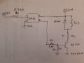
I am searching for the lowest input current optocoupler to turn on led.
I have tested 4N35, it has 0.3mA, but I want a low current possible.
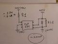
I have 5Vdc input, speed is not a problem, it works in DC only.
focus is to turn on a 12Vdc relays on the transistor side.
Do you have some suggestions for the right component?
I am searching for the lowest input current optocoupler to turn on led.
I have tested 4N35, it has 0.3mA, but I want a low current possible.
I have 5Vdc input, speed is not a problem, it works in DC only.
focus is to turn on a 12Vdc relays on the transistor side.
Do you have some suggestions for the right component?