Facebook
 Google
 GitHub
 Linkedin
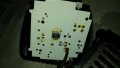
Hi there i was wondering if there is a way to identify these leds so as to know their specification and built a new circuit to drive them.
These come from the following video lights
A. http://www.farseeingvideo.com/showproduct.jsp?pid=101
B. http://www.vectshop.com/free-shipping-vect-lbps1800-led-camera-light-p-24.html
The only known data are the color temp that are claimed to be around 5000K.
A.

B.
These come from the following video lights
A. http://www.farseeingvideo.com/showproduct.jsp?pid=101
B. http://www.vectshop.com/free-shipping-vect-lbps1800-led-camera-light-p-24.html
The only known data are the color temp that are claimed to be around 5000K.
A.
B.
") ))
))