Help identifying component

Thread Starter

buttim

Joined Apr 23, 2018
3
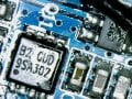
Yes, I tried to google it in many ways. Still no result.
The component sits on a PCB very close to a SIM holder and related GPRS module (should be a Quectel M26).
I suspect the function might be an LDO that can be enabled/disabled to power on/off the GPRS module. Definitely not sure though.

Any kind soul wanting to help?
 

Attachments

ebp

Joined Feb 8, 2018
2,332
If you are talking about the 8-pin device labeled Q11, I suspect it is a FET, possibly a dual, but I can't see enough detail to have any certainty. It may function as part of a regulator circuit, but more likely just a switch. "Q" is the traditional prefix for a transistor, with no regard for what type (BJT, JFET, MOSFET, sometimes SCRs, etc).
 

Thread Starter

buttim

Joined Apr 23, 2018
3
Didn't even think about looking at the board instead of the component! This definitely makes sense. Do you know of any half standard pinout for such components? I'm not really interested in the electrical features but just how to turn the beast on from the MCU on the board
 

ebp

Joined Feb 8, 2018
2,332
If it is a single FET, typically pins 5-8 will be the drain, pins 1-3 the source and pin 4 will be the gate. Duals seem to vary more, but 7&8 D, 2 G, 1 S for one, 5&6 D, 4 G, 3 S for the other is one arrangement I've seen. I've never used any in that particular package, just SO-8-like packages. Pinouts may vary more than I think. An AO4484 is an example of an SO-8 pinned as I described.

Look closely at the board, or even check with an ohmmeter for pins that are connected together. Also, if it is a FET or dual, the gate pin will typically have just a narrow track whereas the source and drain tracks will be wider or connect to areas. It looks like pins 1-3 are connected together, but I can't really tell.

If you have diode check function on a meter, and it is indeed a FET, there will be a diode between the drain and source. For an N-channel FET the cathode will go to the drain, for a P-channel the other way around. If it is a "high side" switch for power, there is a pretty good chance it is P-channel, since, given suitable characteristics & operating voltages, it can be turned on by connecting the gate to common (ground). An N-channel would require a high-side driver that would apply at least 2 or 3 volts more positive than the voltage being controlled to the gate. Other things in the circuit may make current paths that may interfere with this measurement.
 
Top