Help - Durable high voltage power supply using Voltage Multiplier

Thread Starter

Phạm Việt Dũng

Joined Aug 29, 2018
13
Hello,
I'm building a high voltage power supply for my Ion thruster project (DC Ionic wind generator) based on the needle-to-cylinder structure below and I'm having trouble understanding the Voltage Multiplier.
I'm needing this HV circuit only for long duration corona discharge in order to create Ion wind.
If you have a better circuit for this purpose, please suggest me, I'm in a very urgent situation and desperately needing your help!

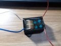
And I'm using this Flyback driver + Full wave voltage quadrupler combination circuit

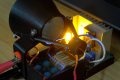
The multiplier sparks it getting weaker than normal when I tested it in needle - cylinder structure (I mainly used it for corona discharge). The other time I connect the circuit with a bigger needle - cylinder structure and it generates much stronger Ion wind but then suddenly stop after operating in less than 5 sec, the multiplier has just burned out. And sometimes it just stopped working and gives louder "zzz" sound, I then have to unplug and then replugged it again. I only have a few fundamental about power electronic but the Multiplier behavior is too much for me to predict.

For my multiplier I'm using:
Input voltage (from flyback transformer) around 10-20Kv
High voltage diode: TL74A 20kV 5mA
High voltage cap: 101 25Kv
 

Attachments

-live wire-

Joined Dec 22, 2017
959
Maybe consider a dual resonant tesla coil. They can get very big and powerful HV arcs. Alternatively, try connecting some neon sign transformers in parallel on the input and in series on the output. That could get very high voltages. But given that the current can be lethal, PLEASE DO NOT DO ANY OF THIS UNLESS YOU ABSOLUTELY KNOW WHAT YOU ARE DOING. But what is the exact desired output current and voltage? That will help us in determining the best circuit.
 

Thread Starter

Phạm Việt Dũng

Joined Aug 29, 2018
13
Maybe consider a dual resonant tesla coil. They can get very big and powerful HV arcs. Alternatively, try connecting some neon sign transformers in parallel on the input and in series on the output. That could get very high voltages. But given that the current can be lethal, PLEASE DO NOT DO ANY OF THIS UNLESS YOU ABSOLUTELY KNOW WHAT YOU ARE DOING. But what is the exact desired output current and voltage? That will help us in determining the best circuit.
Thank you for being here at this moment,
I can't use the Tesla coil because of dimension limited, the Ion thruster I'm building is for a mini satellite project so there's not enough room.
As I read about Ion wind generator, the current is not important and it can be as low as possible, however, the Voltage is needed so I decided to use the Voltage multiplier circuit. The arc I generated before was about 3cm and the corona wind came out so strong, (strong enough for my project at least since it's enough to blow out candles flame).
I started to wonder about the capacitor's value I used, is it quite too small?
or maybe due to the bad epoxy insulator that I dipped all the flyback transformer and multiplier within? (in the picture I included)
 

Attachments

-live wire-

Joined Dec 22, 2017
959
How much can you spend on it, and what voltages do you want? Generally, weak arcs mean that the capacitors cannot supply enough power. So you could try using bigger capacitors.
 

Thread Starter

Phạm Việt Dũng

Joined Aug 29, 2018
13
How much can you spend on it, and what voltages do you want? Generally, weak arcs mean that the capacitors cannot supply enough power. So you could try using bigger capacitors.
Yes, I want it to consume the lowest power possible, I use only 2 Li-ion 18650 batteries in series for my testing circuit. I measured the operating current is around 2-3A with 7.4V.
The 555 timer I turn between 11-12KHz which lets out the longest arc at 1.5cm at flyback transformer and nearly 3cm after multiplier circuit. The current rating of the HV diode I use is only 5mA so... in previous (before degrading multiplier) circuit that voltage around 40-50kV can generate enough Ion wind thrust for my engine.
 
If you are getting between 10 kvolts and 20 kvolts from your flyback transformer then you need impossibly high voltage diodes and caps in your multiplier circuit.

The multiplier you show is intended to raise 120 volts to 480 volts, not to raise 15 kvolts to 60 kvolts.

As to the wind you are getting, isn't it likely that it is ionized air moving which blows out the candle?
 

Thread Starter

Phạm Việt Dũng

Joined Aug 29, 2018
13
If you are getting between 10 kvolts and 20 kvolts from your flyback transformer then you need impossibly high voltage diodes and caps in your multiplier circuit.

The multiplier you show is intended to raise 120 volts to 480 volts, not to raise 15 kvolts to 60 kvolts.

As to the wind you are getting, isn't it likely that it is ionized air moving which blows out the candle?
Yes, I did use the upper power component for this purpose as mentioned in the beginning:
For my multiplier I'm using:
Input voltage (from flyback transformer) around 10-20Kv
High voltage diode: TL74A 20kV 5mA
High voltage cap: 101 25Kv

And the ionized wind is what I intend to obtain, but I want it much stronger and for some unknown reason, the multiplier circuit degraded so quickly (it became weaker) and many weird behaviors...
 

Thread Starter

Phạm Việt Dũng

Joined Aug 29, 2018
13
Also, the plasma (fire) from a candle or lighter is far more conductive, and can help start a HV arc.
The HV arc in this multiplier I think it's quite normal? Since the main purpose of the multiplier is to generate arc, however, the Mosfet heatsink heating seems a bit much quicker when I draw arc during its operation.
Yah, but again the problem is that after the multiplier burned out, it can still arcing, but a lot weaker (arc length ~1mm) so can you point me out which components are dead diode or capacitor? then maybe I can replace them with upper values since I'm not sure I've used the right values for the circuit.
 

-live wire-

Joined Dec 22, 2017
959
The HV arc in this multiplier I think it's quite normal? Since the main purpose of the multiplier is to generate arc, however, the Mosfet heatsink heating seems a bit much quicker when I draw arc during its operation.
Yah, but again the problem is that after the multiplier burned out, it can still arcing, but a lot weaker (arc length ~1mm) so can you point me out which components are dead diode or capacitor? then maybe I can replace them with upper values since I'm not sure I've used the right values for the circuit.
Why not get a multimeter and measure them? If a diode measures as a short then it is probably dead. Also same for a capacitor. For a capacitor, you can also try and see if the measured capacitance is close to the real capacitance.

Have you considered one of these things? Their claims are often BS, but you can usually get at least a few 10s of kv.
 

Thread Starter

Phạm Việt Dũng

Joined Aug 29, 2018
13
Unfortunately, those component are dipped in rigid block of epoxy so I can't hand on with it...
I took my multimeter and measured the epoxy resistance this morning and realize that it's only about 12M ohm for 1mm !!. So I guess I know where I'm wrong now, I highly believe it's due to bad epoxy glue that I bought. So that the charge build-up high in capacitors during corona discharge then break down the epoxy wall and fried it.
I'll build another version soon, with carefully selected epoxy, but I just wonder: do I need to place the HV tolerance resistor across the load? Isn't the corona discharge is good enough for discharging the HV capacitor?
 
Top