Help & Advice needed swapping PCB switches around

MisterBill2

Joined Jan 23, 2018
18,167
I just tried adjusting temperature with both sides simultaneously but only one goes up. Doesn't recognise both of them at the same. The side that goes up is the button that gets pressed the first
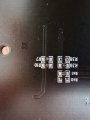
That implies that it is only one input for the control. That will be simple to verify, and I hope that I am wrong with that evaluation. It can still be either way, possibly. The resistance check will verify if there are two inputs or only one input and different resistances for each button.
 

MisterBill2

Joined Jan 23, 2018
18,167
The buttons are connected to the traces by plated through holes. That is very common.
If only the temperature buttons are involved, you only need to move four resistors, so the task is not huge. First, use the ohm meter to discover which side of each switch needing changing is the common. Then discover which connector pin it goes to.
Next, using pointy probes, check which resistors are connected to the buttons whose functions you want to move. Carefully probe the other sides of the resistors already found, and see if the other side of those resistors Are all common to each other, OR only grouped driver and passenger. Now you can discover the values of the four resistors, and which function is at which location. Now get the tweezers and the pointy soldering iron and the serious magnifier.
The project will be to unsolder and exchange the driver and passenger side resistors. Then locate the resistors for lowering the passenger side temp. Just unsolder and swap those two resistors. That is all there is to it, except to verify the swap worked. MORE TOMORROW WHEN i AM BACK AWAKE.
 

Thread Starter

john2k

Joined Nov 14, 2019
219
@MisterBill2 sorry for late reply on this, I was busy fixing other things. I've finally managed to sit down and analyse the pins with the multimeter. There are quite a lot of backlight LED's on the board as well as some other buttons to turn A/C on and off etc. All the switches and LED's seem to share the same single Ground pin. What I have discovered is that the 4 buttons (2 pairs of buttons that I want to flip around are on a dedicated pin along with the front and rear de-misters. All the other buttons are on different pins. I've attached a picture of my multimeter so that I can refer to it.

Most of the ohm readings I was able to get from the buttons using the 20K ohm setting on my multimeter except the temperature down on the right side which gives error because it's exceeding the reading.

So on 20k Ohm setting on the multimeter I am getting the following readings when I press the button:

Left Side:
Increase Temperature: 2.70
Decrease Temperature: 4.68

Right Side:
Increase Temperature: 12.52
Decrease Temperature: Exceeds 20k setting Error

So then I did the test again on 200k Ohm setting and got the following readings

Left Side:
Increase Temperature: 02.6
Decrease Temperature: 04.6

Right Side:
Increase Temperature: 12.4
Decrease Temperature: 26.9

Below is a pic of my multimeter as well as a pic of the rear of the PCB. There are loads of resistors. Where do I begin? how do I know which 4 resistors I need to swap to where?

board20220714_133846.jpg


MisterBill2

Joined Jan 23, 2018
18,167
GOOD NEWS! At least, sort of good news. That means that to exchange those functions would only require exchanging those resistor pairs. So now the task will be to determine which four resistors and locations are which, and then unsolder the resistors and exchange their positions, and solder them in the new locations. Surface mount resistors will be much simpler to remove than four leg thru-hole switches. Unless they have been glued in place prior to soldering. An alternative is to cut the runners and add jumper wires. That might possibly be much simpler. If the runners can be accessed. That conformal coating looks rather solid.
 

Thread Starter

john2k

Joined Nov 14, 2019
219
I've attached some high quality zoomed in photos of the resistors. I've also noticed a component label Q1 and Q2. I know the resistors are numbered with the letter R. Not sure what the Q1 and Q2 components are.

I tried to measure the resistance of the resitors just by touching each side using the multimeter but i am not getting any reading. The resistors seem to have some sort of number written on them but doesn't seem to reflect a ohm reading.

You suggestion about cutting the runners I think will be too risky :) What about my original suggestion of just competely de-soldering the single legs of the switch that make the connection when pressed and then use the trace repair copper wire to run from one side to the other. Essentially just patching them over ?
 

Attachments

Thread Starter

john2k

Joined Nov 14, 2019
219
Looking at the numbers on prited on the resistors themselves. it appears they represent a ohm value. So I calculated the cloest and it appears these are the numbers I might need to be looking for

272 = 2.7k - Left Up
472 = 4.6k - Left Down

133 = 13k - Right Up
273 = 27k - Right Down

Looking at my PCB, I found a pair of resistors on top of each other R41, R39 and they seem to match the left up and down. And then for the right I found another pair next to each other R48 and R50 which seem to be 133 and 273 on top of each other. There are some of the numbers elswhere but these two seem on top of each other and is it a coincidence or ar they the ones i'm looking for? The is another 472 next to the Q2 too.

If i de-solder the resistors, do they have a polarity or can the go on either way round? The closest resistors for this seem like the 0603 size. So I've ordered some spare 10 of each. 10x 2.7k, 10x 4.7k, 10x 13k and 10x 27k. Should I re-use existing resistors or wait until new ones come? Can the heat from desoldering and resoldering it cause them to damage so maybe better to use new ones?

I could try and desolder one resistor and see if it effects the button in question?

Also, the pairs of resistors that I've located on top of each other seem to match the sides. So for the right side switch behind it there are two resistors on top of each other 133 and 273 and for the left side there are the other two 272 and 472.
 
Last edited:

MisterBill2

Joined Jan 23, 2018
18,167
Resistors do not have a polarity, and so you are safe there. Andunsoldering a resistor will be FAR more likely to succeed than anything you can do with one of those button switches, or even anything that I could do with them.
You will need some solder-wick and a small point iron, and also a magnifier. You will also need some good tweezers. I have no ideas about your soldering skills, so I suggest getting a scrap circuit board and unsolder some surface mount resistors to gain experience.
 

Thread Starter

john2k

Joined Nov 14, 2019
219
Thank you @MisterBill2 just a quick update on this. I've managed to remove the resistors. I didn't have magnifiers available but I have a set of tweezer soldering iron. I applied a dab of flux on each solder point of the resistors and they simply lifted off nicely with the tweezers with a clean pad remaining. I removed one resistor at a time and then tested the ohm reading to make sure the relevant button I suspected that resistor to be stopped giving a reading when I pressed it. All 4 were correct as predicted. I then soldered on new resistors in opposite way and then tested the ohm readings and it's now flipped like I wanted it. The ultimate test will be when I plug it into the car and if it's successful or not. Plan to do that in the next few days. Will update with results.
 

MisterBill2

Joined Jan 23, 2018
18,167
"New Resistors"?? Or do you mean new to the location? Chip resistors are usually reusable. Tweezer irons are certainly the recommended tool for removing those devices. And it was far simpler than moving the buttons. So on top of learning a bit you also saved a fair amount of money, making it some good news.
 

Thread Starter

john2k

Joined Nov 14, 2019
219
I re-used 2 resistors and put two new ones in because two of them stuck to the soldering tweezer for a bit longer than I'd like so exposed to more heat so just wanted to play it safe seeing as I bought backup resistors just incase it went wrong. I measured the resistance of the new ones and it matches old ones and the number written on the resistors match too
 

Thread Starter

john2k

Joined Nov 14, 2019
219
@MisterBill2 there seems to bit a slight hiccup now So although swapping those resistors solved the issue and has given me the correct orientation for the temperature buttons. I now have a very strange issue. My unit has 3 pcb boards as pictured below. The big PCB board at the bottom with the two red squares are the buttons I managed to get working. The two small boards are connected to the main board's small connector as indicated with the blue line. The small board with the blue square has 4 additional climate control related buttons which now seem to conflict with some of the climate buttons on the main board. If i leave that left small board disconnected then the main board has no conflict. That small board has 4 wires, two are for the LED backlight and the other two are for the buttons. Something has caused some sort of confusion. Any suggestions on how I can overcome this and figure out what is wrong? I am assuming because of the resistor changing, it has somehow effected the resistance values of the buttons that are not working. Like i said, if i leave that 4 pin connector board disconnected then it seems to work fine.


MisterBill2

Joined Jan 23, 2018
18,167
Oh Wow!! Very interesting indeed. A whole another challenge. Are these boards also for driver and passenger sides? And now they are also in need of exchanging sides?? or is it something else? If they only have four wires and two are for the lighting, then it must be that they also connect resistors across the other pair of wires.
But first, I suggest using a bright light and a good magnifier and carefully examining the main board to check for any accidental solder bridges. Not that I suspect that, but it is a simple thing just in case and it is not likely to cause a problem.
Certainly there may be a side for side confusion, especially if there are buttons on both the big board and the small boaed that must be pressed at the same time.
 
Last edited:

Thread Starter

john2k

Joined Nov 14, 2019
219
Oh Wow!! Very interesting indeed. A whole another challenge. Are these boards also for driver and passenger sides? And now they are also in need of exchanging sides?? or is it something else? If they only have four wires and two are for the lighting, then it must be that they also connect resistors across the other pair of wires.
But first, I suggest using a bright light and a good magnifier and carefully examining the main board to check for any accidental solder bridges. Not that I suspect that, but it is a simple thing just in case and it is not likely to cause a problem.
Certainly there may be a side for side confusion, especially if there are buttons on both the big board and the small boaed that must be pressed at the same time.
I will check and report back. The smaller boards are not side specific. It's just the left board that controls climate stuff. The right board is just shortcuts to functions of the head unit like mute, source etc. Those seem to work fine. The 4 extra buttons that the left board provides is fan speed + & - then dual climate and airflow direction. If I connect that board then my climate OFF and AUTO buttons on the main board seem to not function correctly. The auto button ends up turning dual on and off and the off button ends up adjusting airflow direction.
 

MisterBill2

Joined Jan 23, 2018
18,167
Did these buttons function correctly before? Is it possible that wit none of the buttons pressed on the main board, some resistance is now present, while before it was not?It seems like the wrong commands are being sent, which points toward some button being stuck "ON". so some resistance checking work is in order.
And the symptoms describe almost point at getting a connector reversed somehow. That can happen.
 
Last edited:

Thread Starter

john2k

Joined Nov 14, 2019
219
So i did some testing with the multimeter. There is no way it's linked to the resistors I changed. Because the resistors i changed is tied to a completely different pin. And the buttons that are conflicting from the side board are on a different pin and share with AUTO, and Off.

So what I did was isolated that side board, and tested the pin and recorded the values of the resistance when pressed. I then connected it to the main board and checked if it changed the values of the AUTO and Off buttons but it didn't but then all of a sudden my multimeter was continously giving a ghost reading of about 115 to 145k even though i was pressing anything. So then I unplugged the side board and the ghost presses disappeared. I then just isolated that side board again and left the multimeter plugged in and the ghost presses was still appearing. So it appears this board is acting up. The only thing I changed on these small board is the 4 backlight LED's and the LED's are not tied to the same pin so I doubt LED changes are causing this. Plus the LED's only light up when headlights are on.

Any ideas how I can go about finding what is causing the ghost pressing? The strange thing is that the resistance value total doesn't even sum up to the total values of the buttons. The 4 buttons have a value of 12.88k, 4.69k, 1.5k, 2.76k
 

MisterBill2

Joined Jan 23, 2018
18,167
so the good news is that there is no damage to the main board that you worked on. That is a relief. Ghost readings would most likely come from some sort of conductive substance on the board, or possibly under the switches. If the boards were OK before, then it may be something that happened while changing the back light LEDs.. Excess solder flux? spilled soft drink?? Sweat? Fingerprints?? or possibly a stray bit of solder??
A close examination seems to be in order now. And possibly a cleaning with alcohol or maybe flux remover.
Is there any chance that something was overheated?
 

Thread Starter

john2k

Joined Nov 14, 2019
219
so the good news is that there is no damage to the main board that you worked on. That is a relief. Ghost readings would most likely come from some sort of conductive substance on the board, or possibly under the switches. If the boards were OK before, then it may be something that happened while changing the back light LEDs.. Excess solder flux? spilled soft drink?? Sweat? Fingerprints?? or possibly a stray bit of solder??
A close examination seems to be in order now. And possibly a cleaning with alcohol or maybe flux remover.
Is there any chance that something was overheated?
I am inspecting that board to see and will report back. I have a question about the resistance measurements on the multimeter. The other boards that work fine, if I put resistance value on multimeter to 200M then it seems to read a value even though I haven't pressed the button and the value seems to very gradually drop bit by bit but then when I press the button it goes to the correct value. Is that normal?

The board with the issue, the values just jump up and down with no one consistency.
 

Thread Starter

john2k

Joined Nov 14, 2019
219
I just cannot see anything visual that can be causing this. Basically I have the multimeter set to ohm reading at 200k and then I have the red probe hooked up to the pin that's supposed to give a reading when you press a button. I have the black probe on the ground. Just like how I'm testing the other boards. But this one for some reason even without pressing any button gives a number that's constantly jumping up and down. If I press the button down then I get the correct reading. But it seems the car doesn't like it that because the constant fluctuating reading seems to be confusing the car
 

Thread Starter

john2k

Joined Nov 14, 2019
219
Ok, so might have narrowed down issue to somewhere at the top of the board. The top button is airflow direction button. Behind each button is the resistor that activates that button. So I de-soldered the resistor that is linked to the air circulation button and so far I'm not having any ghost readings. So somewhere around there is the issue or maybe that resistor itself is faulty? But how could it have happened?
 
Top