Facebook
 Google
 GitHub
 Linkedin
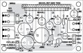
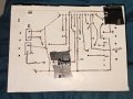
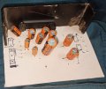
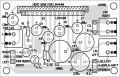
Hey its me again  and this time with LA4440. Have a look at the pcb diagram, and i tried to mimic the diagram using cardboard and copper wire strips (2 resistance would be added later). The copper wire strips i took is from The leftover of a thick electric cable that's used in my home's main switch terminal and we're also using these as a fuse wire on our wall boards. My question is, would that cause any resistance issue to my circuit? I mean those strips might heat up and change the circuit's total impedance?
and this time with LA4440. Have a look at the pcb diagram, and i tried to mimic the diagram using cardboard and copper wire strips (2 resistance would be added later). The copper wire strips i took is from The leftover of a thick electric cable that's used in my home's main switch terminal and we're also using these as a fuse wire on our wall boards. My question is, would that cause any resistance issue to my circuit? I mean those strips might heat up and change the circuit's total impedance?Attachments
-
 1.7 MB Views: 25
 -
 2.2 MB Views: 23
 -
 54.7 KB Views: 23