Hall Sensor, specifying

Thread Starter

#12

Joined Nov 30, 2010
18,224
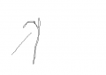
Here we have a magnet in a wheel. A sensor has 17 VDC applied to one terminal. The second terminal alternates between 5V and 0V. No magnet, 5V. Yes, magnet, 0V. The third terminal is obviously what I called, "common". Everything that is not the magnet or the sensor is either plastic or water. (It's a water meter of sorts.) The axis of the magnet is parallel with the axis of the wheel. It is counterbalanced with a plastic mass, but I didn't draw that part.

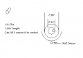
I want to find that sensor as a TO-92 or an SMT-3

What do you call it?
About how many gauss is the correct range?
What kind of circuit would be connected (assuming this makes an input for a microprocessor).

It seems strange to me because of the 5V output when no magnet is applied.
A range of Vcc causes a 5 volt output unless it is zero volts?
It passes current when no magnet is nearby, but the voltage is clamped to the 5V line with a diode, and the sensor stops passing current when a magnet is nearby and the voltage falls to zero because of a resistor to ground?

Obviously, I don't have a clue how to measure the magnetic field and can not understand the myriad devices available as Hall Effect sensors.

A partial answer will be helpful.

Number Twelve.
 

Attachments

Thread Starter

#12

Joined Nov 30, 2010
18,224
With open collector, you could just switch the output itself to 5v .
I don't have a choice about the circuit. I'm hacking a water softener and do not wish to cut into the circuit board. I just want to stop paying $40 for a Hall sensor when it fails.
 

MaxHeadRoom

Joined Jul 18, 2013
28,617
Are you sure this is not the way it is being used now, with a open collector pulled up to 5v?
With no magnet the output would be 5v with a O.C. NPN device.
Max.
 

Thread Starter

#12

Joined Nov 30, 2010
18,224
It seems to me that an open collector sensor would only need two wires. If a three wire Hall sensor is wired as an open collector, how does it have ground on pin one, 17 VDC on pin three, and 5V on pin two, then pin two converts to zero volts when a magnet is near?

Another doubt. The PDF you posted says it works with alternating poles or a repetitive south pole, but sensing the side of a bar magnet doesn't seem like a pole at all. It just seems like flux arcing from one pole to the other. What is that called? Unipolar? Bipolar? Just some gausses?
 

Thread Starter

#12

Joined Nov 30, 2010
18,224
That certainly looks like it does what I need. If the circuit board is designed for it...
The Vcc has nothing to do with the output voltage being 5 volts, it is merely, "open".
Probably that pin is pulled high on the board with something like 10K from Vcc = 5V.
When a magnet approaches, the chip shorts the output to ground.

I will get out my microscope and see if I can find any numbers on the corroded chip.
I sure never imagined chopper stabilized all kinds of stuff in a SOT23 pkg. All that for zero and one?
There must be uses that need something besides zero and one to need all that extra stuff.
 

Alec_t

Joined Sep 17, 2013
14,280
A lot of unknowns, but given that the Earth's mag field is ~ 0.5 gauss, I'm guessing that your magnet's field would be several gauss at the sensor position.
 

MaxHeadRoom

Joined Jul 18, 2013
28,617
The Vcc has nothing to do with the output voltage being 5 volts, it is merely, "open".
Probably that pin is pulled high on the board with something like 10K from Vcc = 5V.
When a magnet approaches, the chip shorts the output to ground.
.
That is what I implied.
The different types are bipolar = respond to either pole, Unipolar = respond to one polarity only, Latch/Unlatch = require one pole to latch and stay latched until reverse pole unlatches.
Max.
 
Last edited:

AnalogKid

Joined Aug 1, 2013
10,986
Thanks to that stoopid Mic hael Faradsy there is no such thing as a DC transformer. A Hall sensor is as close as it gets.
Unlike a current transformer, a Hall sensor can respond to DC. Also unlike the transormer, the output wanders all over the place with temperature. We use closed-loop Hall sensors, and even with external gain and offset trims we can get only two real digits out of our 3 digit display.

Range, polarity, sensitivity, blah blah... All Hall sensord cook down to analog or digital output; the rest is application dependent. If you know what the board wants, you probably can find a part to supply it.

The Hall signal is very low level and can go down to DC, so it is the perfect candidate for a chopper stabilized amp. The smaller the Hall element is the more sensitive it is, but also the more it's sensitivity changes with temperature. Hence the AGC. The good news is that once you pile on all of that circuit stuff, you have something that will operate flawlessly for 20 years from -40 F to + 200 F bolted to a car engine, and you can put 100 million of them into the field with infinitessimal failure rates.

ak
 

eetech00

Joined Jun 8, 2013
3,856
A lot of unknowns, but given that the Earth's mag field is ~ 0.5 gauss, I'm guessing that your magnet's field would be several gauss at the sensor position.
Hi

I have an Gauss meter app on my iPhone. When sampling is turned on..it reads 0.451 Gauss.
If I measure a small magnet...it reads about 2.7 gauss. Don't know how accurate it is but maybe it can be used to measure the field?
 

Thread Starter

#12

Joined Nov 30, 2010
18,224
Thanks for the help. The last time I looked at Hall Sensors, they were just then being invented and acted more like an opto-transistor: two leads and something magic made them shift their conductivity. Now they are more like an op-amp in a SOT.

After sleeping, I see that the Honeywell part should work. Yesterday, I needed AK and the Allegro PDF to move me out of the stone age on this subject.

The gausses...there must be a lot more than 10 or twenty to lift a wrench 5 ounces off a postal scale before the magnet loses its grip. Then, the sensor is about 0.35 to 0.4 inches away from the edge of the magnet. Any guesses about the gausses?
 

Thread Starter

#12

Joined Nov 30, 2010
18,224
I have an Gauss meter app on my iPhone. maybe it can be used to measure the field?
First, I would have to buy an iPhone. :rolleyes:
Then I would have to stick it in a 5mm hole. I don't think it would fit, or keep this project under $40.
 

MaxHeadRoom

Joined Jul 18, 2013
28,617
Although maybe not very a scientific approach, at a $1.50Ea it would not cost much to bring a couple in and experiment, From my experience it would be a very weak magnet that did not work on any of the versions.
I have used several versions of the SS400 series and although I have typically used miniature Neodymium magnets I would be surprised if they did not operate at .4".
Max.
 
Last edited:

Thread Starter

#12

Joined Nov 30, 2010
18,224
Yeah, I kinda figure there have been so many improvements lately that it shouldn't be difficult to find something that would work on a 12 year old water softener, and I sure like $1.50 instead of $40!
 

MaxHeadRoom

Joined Jul 18, 2013
28,617
Generally hall effect sensors that use a P.M. detection have a larger detection range than the hall proximity type that detect a simple ferrous or non-ferrous metal flag.
Max.
 

Thread Starter

#12

Joined Nov 30, 2010
18,224
Another aspect is the change in distance. The sensor must deactivate when the magnet is on the far side of the rotation. Anybody know a formula for the weakening of the magnetism across distance? It's only moving from 0.4 inches to 0.8 inches away from the sensor.
 

Kermit2

Joined Feb 5, 2010
4,162
placing the sensor with an angle to the axis of rotation will reduce the sensitivity of the device. So you can always twist it slightly out of line to make it less responsive to the magnet.
 

Thread Starter

#12

Joined Nov 30, 2010
18,224
Marking is something 41E.
The left mark looks like a distorted question mark with a diagonal line running down to the left.
Of course, the diagonal line might be a scratch...and it might not.
 

Attachments

AnalogKid

Joined Aug 1, 2013
10,986
Another aspect is the change in distance. The sensor must deactivate when the magnet is on the far side of the rotation. Anybody know a formula for the weakening of the magnetism across distance? It's only moving from 0.4 inches to 0.8 inches away from the sensor.
Inverse square might be a good starting point, depending on the material the magnet is mounted in.

ak
 
Top